The purpose of this tutorial is to demonstrate the simulation of cardiovascular solid mechanics problems with oomph-lib. We showed in another tutorial how to use VMTK together with oomph-lib's conversion code
to generate unstructured fluid and solid meshes for the simulation of physiological fluid-structure interaction problems based on data from medical images. Here we show how to study the deformation of the vessel wall (which was assumed to have a constant thickness when the solid mesh was generated from the imaging data) when subjected to a pressure loading. The problem serves as a "warm-up problem" for the corresponding fluid-structure interaction problem in which the elastic vessel conveys (and is loaded by) a viscous fluid.
We stress that the tutorial focuses on the implementation aspects, not the actual physics. Since the driver code discussed here is also used in the library's self-tests we deliberately use a very coarse mesh and apply very simplistic boundary conditions. The results shown below are therefore unlikely to bear much resemblance to the actual deformation of a blood vessel in vivo. The section Comments and Exercises at the end of this tutorial provides several suggestions on how to make the simulation more realistic.
The problem (and results)
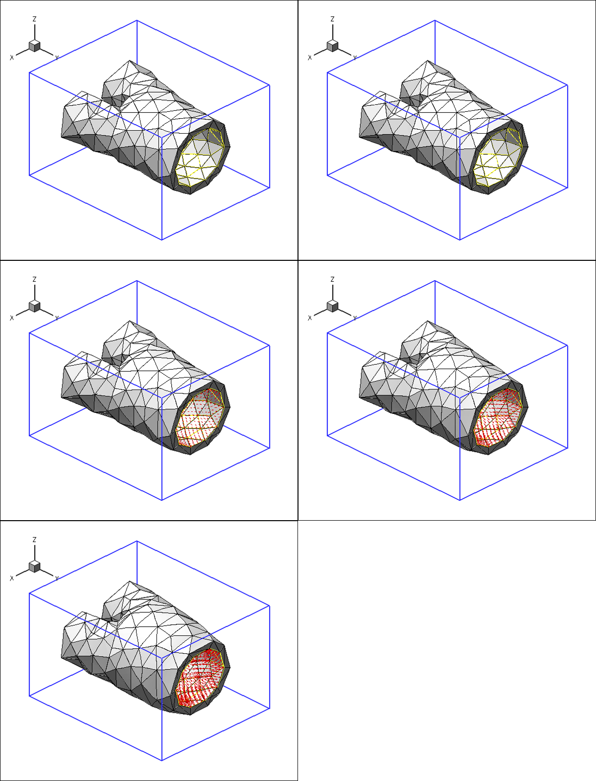
Here is an animation of the problem: An elastic blood vessel is loaded by an internal pressure while its "ends" are held in a fixed position. As the magnitude of the pressure load is increased the vessel inflates:

The blue frame surrounding the vessel is drawn to clarify its spatial orientation. The yellow edges show the boundaries of the internal faces via which the pressure loading is applied, and the red arrows indicate the direction and magnitude of the pressure loading.
The driver code
The driver code is practically identical to the one discussed in another tutorial. In fact, the two codes only differ in the specification of the names of the tetgen files that describe the unstructured fluid mesh, and the enumeration of the boundaries. We also disabled the gravitational body force. Therefore, we will not discuss the driver code in detail.
Comments and Exercises
Generating finer meshes
As acknowledged at the beginning of the tutorial, the solid mesh is far too coarse for the simulation results to be accurate. As an exercise, follow the instructions in oomph-lib's VMTK tutorial to generate a finer mesh. We are hoping to make the image files used in this tutorial available soon. Please contact us if you can't wait. Remember that you will have to update the enumeration of the domain boundaries if you change the mesh.
Making the boundary conditions more "realistic"
In the example shown above we applied boundary conditions that held the "ends" of the bifurcation in a fixed position. These boundary conditions are obviously rather artificial as no such constraints exist in the human body. Unfortunately, it is not entirely clear how to come up with boundary conditions that are genuinely "more
realistic". One way to ensure that the (inevitably artificial) boundary conditions have a weak(er) effect on the deformation of the "region of interest" would be to attach "flow extensions" to the in- and outflow cross-sections, using the technique described in oomph-lib's VMTK tutorial. Alternatively, we could constrain the displacement of a much smaller number of material points – rigid body motions can be suppressed by pinning the position of just three nodes. We encourage you to explore these options yourself.
Source files for this tutorial
- The source files for this tutorial are located in the directory:
demo_drivers/solid/vmtk_solid/ - The driver code is:
demo_drivers/solid/vmtk_solid/vmtk_solid.cc
PDF file
A pdf version of this document is available. \