The Vascular Modeling Toolkit is a collection of libraries and tools for the 3D reconstruction, geometric analysis, mesh generation and surface data analysis for image-based modelling of blood vessels.
This tutorial demonstrates how to open your dataset in VMTK; navigate around a 3D volume; reconstruct the 3D surface of a vascular segment from CT or MR images; process a surface model to generate a mesh; and how to extract the surface mesh. Finally, we demonstrate how to use oomph-lib's conversion code create_fluid_and_solid_surface_mesh_from_fluid_xda_mesh to generate fluid and solid meshes that allow the simulation of physiological fluid-structure interaction problems in which the (assumed constant thickness) vessel wall deforms in response to the fluid traction.
Before starting, make sure that you have VMTK installed on your machine and that you have your DICOM (Digital Imaging and Communications in Medicine) images. Note that this tutorial describes the use of VMTK version 0.8.
For further information on VMTK, please refer to VMTK's home page.
The generation of high-quality computational meshes from medical images is a non-trivial task. The Vascular Modeling Toolkit greatly simplifies this task but it is important to remember that (intelligent) user input is required at various stages of the process. This tutorial does not provide any guidance on this aspect. We simply demonstrate how to generate meshes that can be used in |
Using VMTK: From the MR/CT images to the fluid mesh
Volume of interest
VMTK is capable of reading DICOM directories (which contain the files with .dcm extension). You can open your dataset in VMTK and navigate around the 3D volume with:
where dicom_directory is the path to the directory containing the .dcm files.
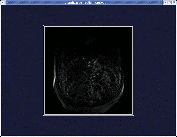
Once the viewer pops up, you can:
- Rotate the volume by left-clicking anywhere on the render window (outside the image).
- Translate the volume by middle-clicking anywhere on the render window (outside the image).
- Zoom the volume by right-clicking anywhere on the render window (outside the image).
- Probe the image planes (coordinates and graylevel) by left-clicking on them.
- Move through the image planes by middle-clicking on them.
- Change the window-level by right-clicking on image planes.
- Quit the viewer by pressing
qore.
You can extract a volume of interest (VOI) from a dataset with :
where the argument to the -ofile option specifies the output file name.
When the render window pops up, pressing i will activate the "interactor": a yellowish cube will appear that is used to select the VOI.
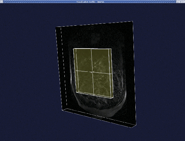
- Translate the cube by middle-clicking on it.
- Resize the cube by left-clicking and dragging the little spheres
(handles) on the faces of the cube.
- Normal interaction with the image is still active, so you can still navigate in the image as explained before.
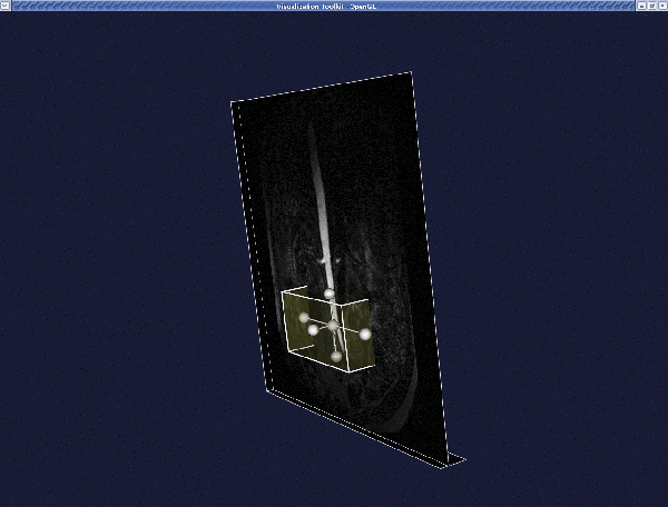
When satisfied with the VOI, press q or e. The new volume is displayed in the render window.
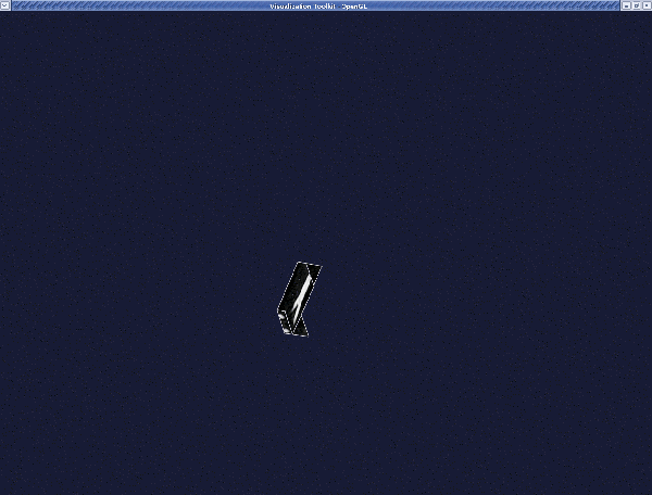
You can quit by pressing q or e, or you can define another VOI by pressing i once again.
The 3D surface reconstruction of a vascular segment
VMTK is capable of generating an image based surface model from a vti file (obtained using the procedure explained in the section Volume of interest above), using the Level Set method and can then extract the surface model using a Marching Cubes algorithm.
First, enter:
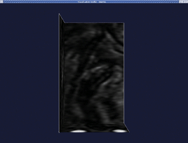
When the VOI is displayed in a render window, press q or e to proceed.
A message will appear on your terminal:
This lets you choose the initialization method used to create the model of the blood vessel. In this tutorial, we will only demonstrate the colliding fronts method. In this method two seeds are placed on the image. Two fronts are then propagated from the seeds (one front from each) with their speeds proportional to the image intensity. The region where the two fronts cross (or collide), defines the "deformable model" – the initial representation of the vessel volume. For further information on this and the other initialization methods, please refer to VMTK's tutorial page.
Now, enter 0 to initialise with colliding fronts.
A message will then appear on the terminal:
Wave propagation, used in the colliding fronts method, can be restricted to a set of intensity levels between two thresholds. Enter the lower threshold, if you want to use one, otherwise enter n. Note that if you don't know the appropriate threshold value you can press i to activate the image and probe it, then quit with q or e when probing is done.
For our example there is no need for thresholds. Therefore enter n.
The next message is:
We repeat the same steps as for the lower threshold.
Next, this message appears:
The render window is now activated. Place the two seeds, one at each of the two ends of a branch. (The geometry of the entire bifurcation is created by "merging" the surfaces of individual branches.) Interact with the image planes to find where you want to place your first seed. When satisfied, left-click on the image while pressing Ctrl. A red sphere will then appear.
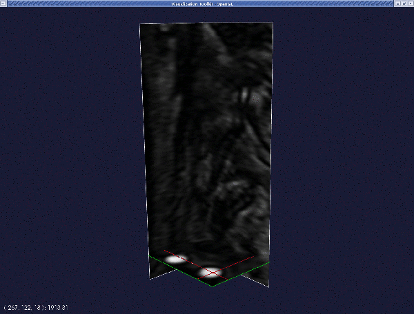
Repeat this procedure for the second seed. Press q or e when done.
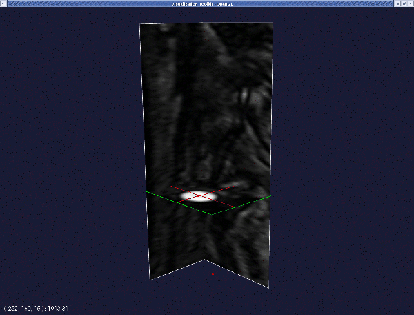
Provided everything went OK, a translucent surface will appear in the render window between the two seeds. This is your initial deformable model.
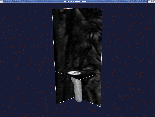
Press q or e to proceed.
Next, you will be prompted with:
If you are not satisfied with your initialisation, enter n to perform it once again, otherwise enter y.
Now press q or e again (in fact, you should do this whenever the system appears to be frozen and the message "Displaying" is shown on the terminal.).
You are now prompted if you want to initialise another branch:
Press n – we will add the other branches later.
The following message will now appear:
These parameters control the deformation of your Level Set:
- Number of iterations is the number of deformation steps the model will perform.
- Propagation scaling is the weight you assign to model inflation.
- Curvature scaling is the weight you assign to model surface regularisation (this will eventually make the model collapse and vanish if it is too large).
- Advection scaling regulates the attraction of the surface of the image gradient modulus ridges.
Based on our limited experience, we recommended that propagation and curvature should be set to 0.0, and advection to 1.0. The number of iterations should be set large enough for the level set not to move anymore (if the region is not too big, try with 300). We encourage you to experiment with these parameters yourself.
Therefore, enter:
The level set will then evolve until the maximum number of iterations is reached. Then the render window will activate, displaying the final model.
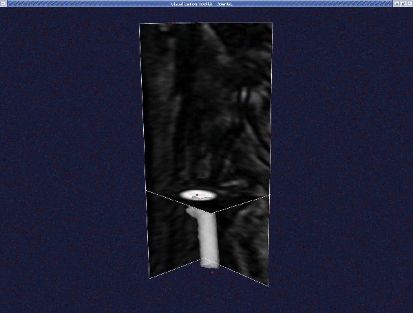
To quit the render window press q or e as usual.
You will then be asked:
If you are not satisfied with your final model, enter n to go back to the level set parameter question. Otherwise, enter y.
Let us assume we are not satisfied, therefore enter n. You will then go back to:
Try again with a bigger curvature scaling:
This yields the following surface:
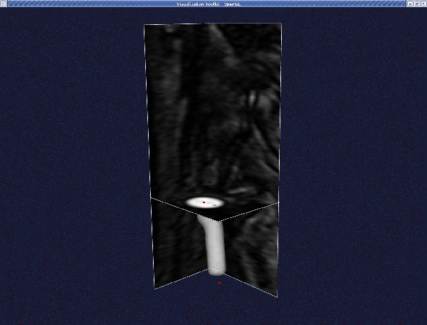
To quit the render window press q or e as usual.
You will then be asked once again:
Assuming we are now satisfied, we enter y .
Next, we receive the prompt:
If you are (still) satisfied with this final model, enter y and this branch will be merged with any branches you segmented before. Otherwise, enter n and this branch will be discarded. (Important: Since this is our first branch we enter y even though no previous branches exist yet!)
The render window will activate, showing you the merged result. To quit the render window press q or e as usual.
Then you will be prompted with:
If you want to segment another branch enter y, otherwise enter n.
Let's segment another branch and enter y. You will go back to :
Exactly the same procedure as described above can be used again. Start by placing your two seeds:
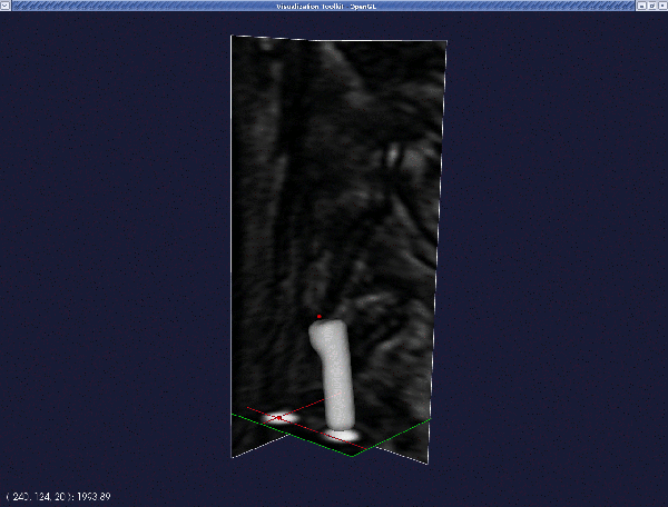
This yields the following deformable model:
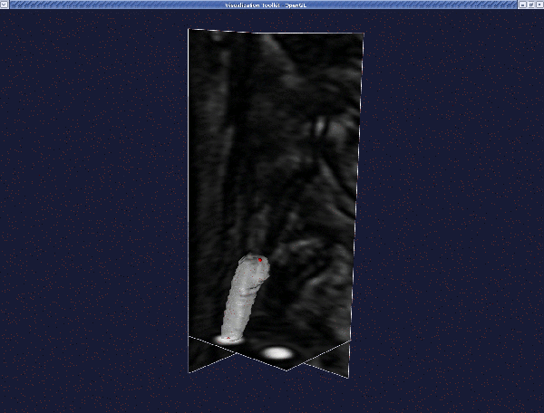
Deform it as before, until you reach the final model:
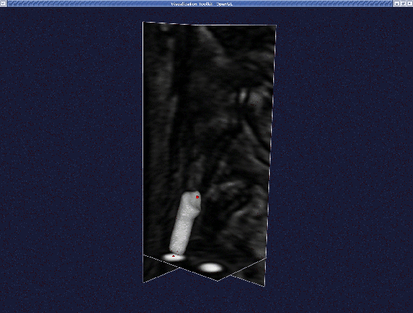
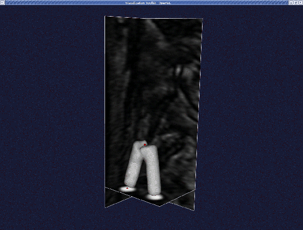
Then when you merge the branches, we obtain this:
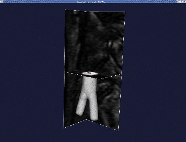
Continue until you have segmented all branches. In our case, we have three branches (we are extracting the surface model of an iliac bifurcation). The final result is:
Now you have a file named level_sets.vti which contains an image. The zero level of this image is the surface you generated. Now we
extract a polygonal surface from it with :
The final surface model is model.vtp which you can display with :
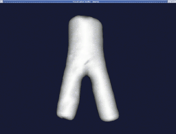
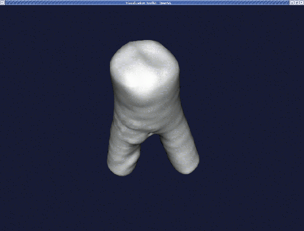
We note that you can add further branches to the level_sets.vti file by using the command
Smoothing the surface
At this point, we have our surface model and we want to generate a computational mesh. In most cases, the surface model has bumpy surfaces, especially if the image quality is not high and if we didn't use the curvature term in the level set evolution. Artificial bumps in the surface can result in spurious flow features and will affect the wall shear stress distribution, so one may want to increase surface smoothness before building the mesh.
You can do this in VMTK with :
There are two parameters controlling the amount of smoothing: passband, which is the cut-off spatial frequency of the low pass filter, and iterations, which is the number of smoothing passes.
For typical vessels, a passband of 0.1 and a number of iteration of 30 should be OK. For example, for the surface model obtained in the section The 3D surface reconstruction of a vascular segment above, the resulting surface is:
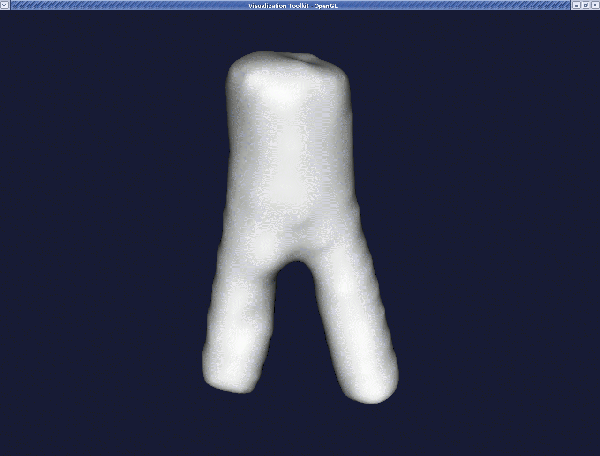
Remember that we can display the surfaces with :
Smoothing with a passband of 0.01 turns this into:
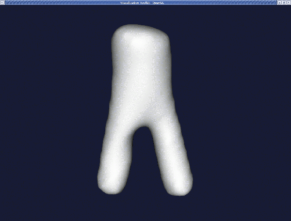
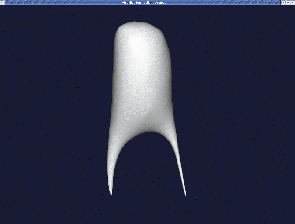
If you want more smoothing, you can increase the passband and/or the number of iterations, but be careful not to remove all surface features by smoothing too much. Also, watch the apex of bifurcations since its curvature may decrease resulting in a shallower apex, affecting the simulated haemodynamics. For example, with a passband of 0.001 and a number of iterations of 100, the result is:
Clipping the endcaps
Once we have created our smooth model, the next step is to open the inlets and outlets, as they are normally closed with a blobby appearance. We proceed by clipping the blobby endcaps with:
When the render window pops up, pressing i will activate the "interactor". A cube will appear (as in vmtkimagevoiselector in the section Volume of interest). Position the cube in such a way that the portion of the surface you want to clip lies inside the cube.
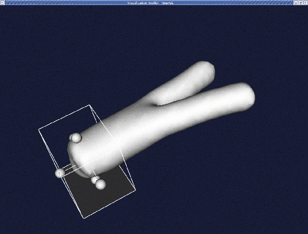
Press the space bar to proceed with clipping.
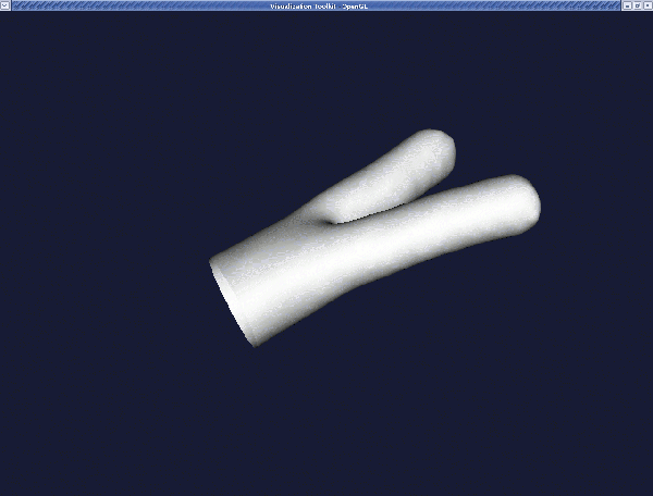
Press i again if you want to clip another piece, or q if you want to quit.
The final result should look like this:
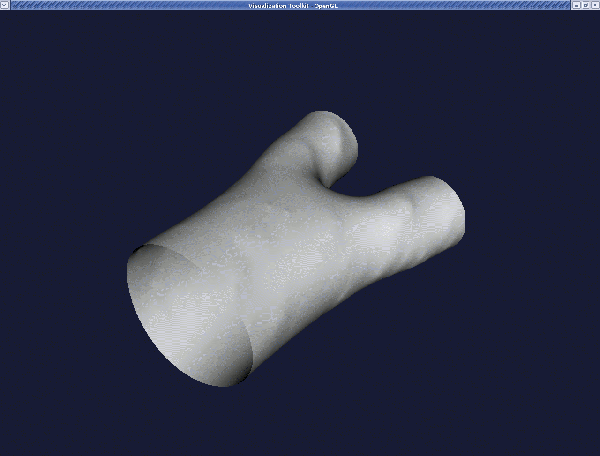
Note that it is possible to clip the endcaps automatically with VMTK. For more information, please refer to VMTK's own tutorial pages.
Adding flow extensions
VMTK provides the option to generate cylindrical extensions to the inlet and outlet cross-sections. These are typically used to ensure that in the numerical simulation, the boundary conditions are applied at a reasonable distance from the region of interest and do not have a strong effect on the flow field. Exactly what sort of boundary conditions to apply and where to apply them is, of course, a non-trivial problem. Nonetheless, the appropriate VMTK command to add the cylindrical extensions is:
where the control parameters are:
adaptivelength(here set to 1) is a boolean flag. If set to 1, the length of each flow extension is made proportional to the mean radius of the vesselextensionratio(here set to 8) is the proportionality factor of the length of each flow extension.normalestimationratio:We suggest setting this parameter to 1. For further information, please refer to VMTK's tutorial page.- The flag
-interactivewas set to0: This means thatvmtkflowextensionswill not prompt the user about what inlet or outlet to extend, but it will perform the task on all the available open boundaries. If you use-interactive1, VMTK prompts the user to specify which boundaries to extend through a graphical window.
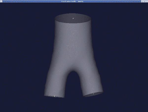
When the render window pops up, before pressing q, make sure you note the different ids of the inlets and outlets. For our example, we see in the figure below that we have one inlet with an id 0 and two outlets with the ids 1 and 2.
A message will appear on your terminal:
Enter the list of ids with a space between them. In our example enter 0 . Next you will receive:
Enter the list of ids with a space separating them. In our example enter:
You can display the resulting surface using:
The result is:
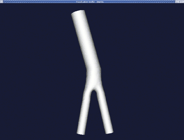
The mesh generation
Finally, we can generate our mesh using the command line:
where the edgelength parameter expresses the nominal edge length of a surface triangle, in physical units. Note that the surface remeshing may fail if you specify a large edge length.
Creating an oomph-lib mesh based on output files generated by VMTK
VMTK exports the mesh for different solvers. The one we chose is the ".xda" format (of LibMesh). To export the mesh in this format enter:
oomph-lib provides a conversion code
which uses the VMTK output mesh in "*.xda" format to generate a file "fluid_*.poly" that can be used to generate the fluid mesh using the open-source mesh generator TetGen.
When executing the conversion code you will be prompted with:
In our example, enter iliac .
To facilitate the simulation of physiological fluid-structure interaction problems in which the vessel walls deform elastically in response to the fluid traction, the conversion code also generates a file "solid_*.poly" that can be used to to generate a mesh for the 3D vessel wall which is assumed to be of constant thickness.
The conversion code therefore requests the wall thickness:
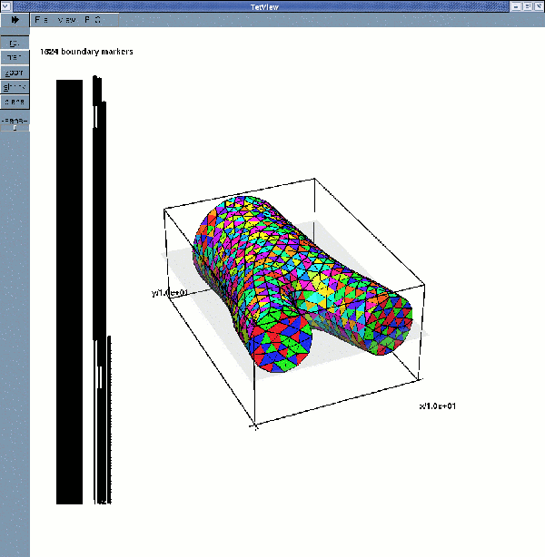
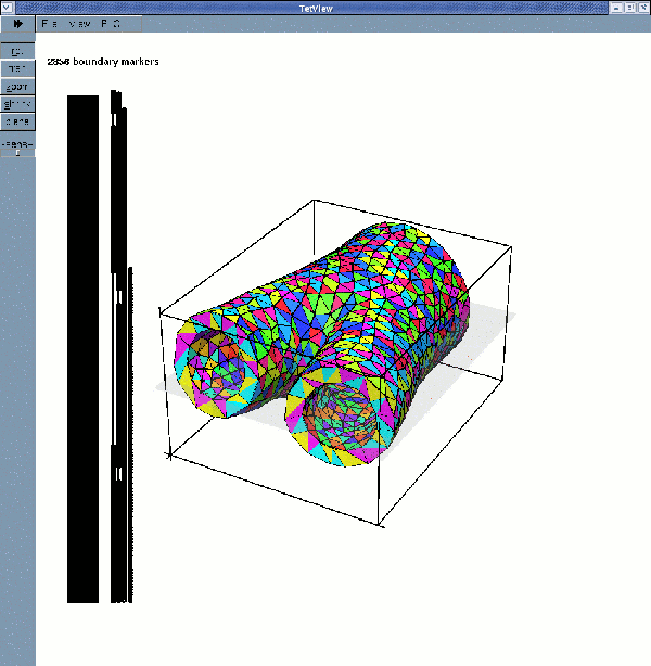
As explained in another tutorial, the consistent generation of surface coordinates in FSI problems requires that all faces with the same boundary ID should be co-planar. For this reason the conversion code provides the option to assign a distinct boundary ID to each surface triangle on the fluid-structure interaction boundary and ensures the IDs are consistent for the fluid and the solid meshes. (The "*.poly" files generated by the conversion code list the relation between the old and boundary IDs at the end.)
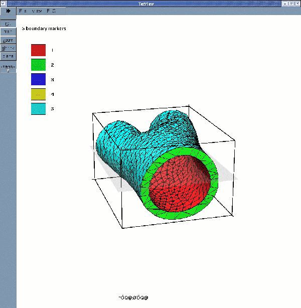
For single-physics problem, however, it is much easier to assign a single boundary ID to each "physical" surface ( i.e. inlet, outlet, vessel boundary). Assuming that we are solving such a single-physics problem we enter n. Two files are now generated : fluid_iliac.poly which contains the fluid domain and solid_iliac.poly containing the solid one.
Tetgen's mesh viewer tetview can now be used to display the surface meshes:
displays the fluid surface mesh with its four boundaries
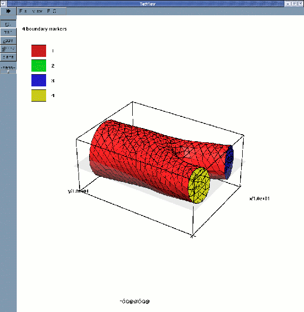
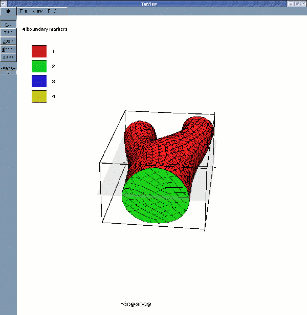
While
displays the solid surface mesh (for a wall thickness of 2mm):
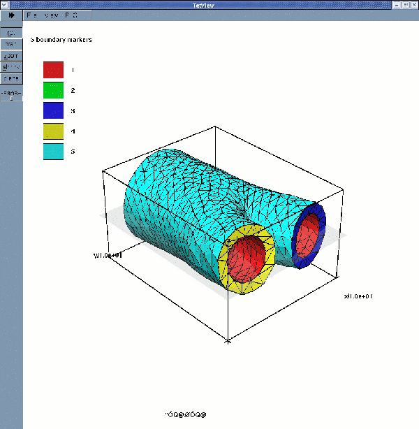
If multiple boundary IDs are requested, the surface meshes are:
Comments and Exercises
- In its current form, the conversion code
demo_drivers/interaction/create_fluid_and_solid_surface_mesh_from_fluid_xda_mesh.cc is restricted to bifurcation-like geometries, and makes certain assumptions about the enumeration of the boundaries. Furthermore, it can only deal with constant thickness vessel walls: the outer surface of the blood vessel is assumed to be parallel to the FSI interface, with the wall thickness being measured in the direction normal to that interface. This simplistic construction can easily create overlapping elements if the apex of the bifurcation is highly curved and/or if a large wall thickness is requested. If this happens tetgen will be unable to generate the solid mesh. It should be easy to modify the code to deal with such cases, however. Get in touch if you need help with this (and feel free to share any improvements with us). - We provide three separate tutorials to demonstrate the use of VMTK-based meshes in
oomph-libdriver codes:- The inflation of the arterial bifurcation by a constant pressure – a pure solid mechanics problem.
- Steady finite-Reynolds number flow through the (rigid) arterial bifurcation – a pure fluid-mechanics mechanics problem.
- Steady finite-Reynolds-number flow through an elastic arterial bifurcation – a fluid-structure interaction problem.
- To facilitate experimentation with the methodology we distribute the
xdafile that was used to create the meshes in the above examples. It is available at:demo_drivers/interaction/vmtk_fsi/iliac.xda
PDF file
A pdf version of this document is available. \