Demo problem: Solid Mechanics using unstructured meshes

The purpose of this tutorial is to demonstrate the solution of solid mechanics problems using unstructured meshes. We focus primarily on two-dimensional meshes, generated using Jonathan Shewchuk's open-source mesh generator Triangle, based on the output from the open-source drawing program xfig. An example three-dimensional problem is described here; see also 3D Problems later in this document.

The solid mechanics problem studied here also serves as a "warm-up problem" for the corresponding fluid-structure interaction problem in which the solid object is immersed in (and loaded by) a viscous fluid.


The problem

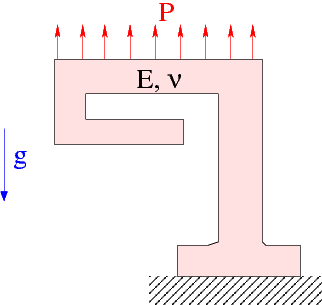
Here is a sketch of the problem: A slightly strange-looking elastic solid is loaded by gravity and by a pressure load, acting on its upper face.
Sketch of the problem.


Mesh generation

We employ the combination of xfig, oomph-lib's conversion code fig2poly , and the unstructured mesh generator Triangle to generate the mesh, using the procedure discussed in another tutorial.

We start by drawing the outline of the solid as a polyline in xfig:
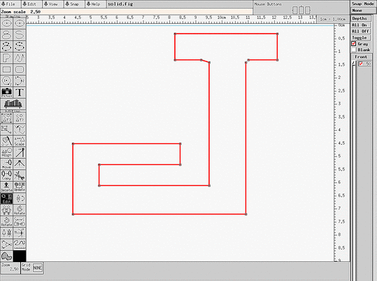
xfig drawing of the solid body.

(Note that we draw the solid upside-down because of the way xfig orients its coordinate axes.)

We save the figure as a *.fig file and convert it to a *.poly file using oomph-lib's conversion code fig2poly (a copy of which is located in oomph-lib's bin directory):

fig3poly solid.fig

This creates a file called solid.fig.poly that can be processed using Triangle. For instance, to create a quality mesh with a maximum element size of 0.025 we use

triangle -q -a0.025 solid.fig.poly

Here is a plot of the mesh, generated by showme distributed with Triangle :
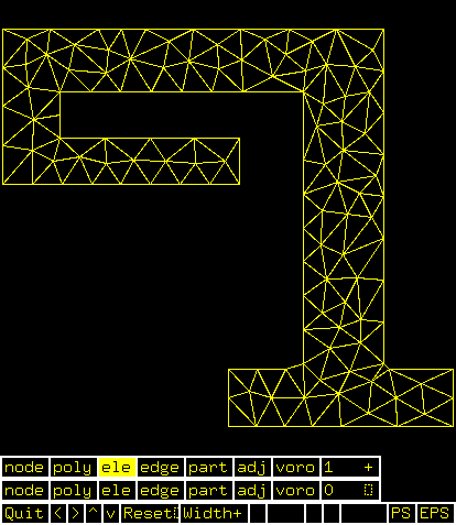
Visualisation of the mesh with showme.

The *.poly, *.ele and *.node files generated by Triangle can now be used as input to oomph-lib's TriangleMesh class.


Results

The animation shown below illustrates the solid's deformation. The first frame shows the undeformed, stress-free reference configuration; the second frame shows the deformation induced by gravity. Subsequent frames illustrate the deformation in response to the (additional) increasing "suction" applied at the upper face.
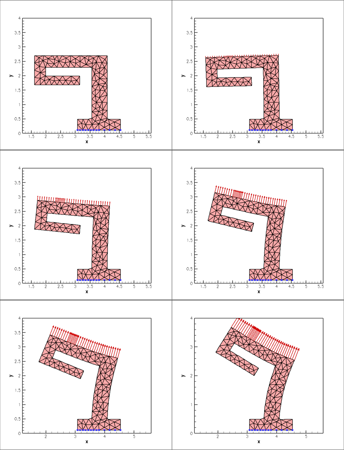
Plot of the deformation.

The blue markers show the position of pinned nodes.


Creating the mesh

We create the mesh by multiple inheritance from oomph-lib's TriangleMesh and the SolidMesh base class:

//================start_mesh===============================================
/// Triangle-based mesh upgraded to become a solid mesh
//=========================================================================
template<class ELEMENT>
class ElasticTriangleMesh : public virtual TriangleMesh<ELEMENT>,
public virtual SolidMesh
{
Triangle-based mesh upgraded to become a solid mesh.

The constructor calls the constructor of the underlying TriangleMesh, and, as usual, sets the Lagrangian coordinates to the current nodal positions, making the current configuration stress-free.

public:
/// Constructor:
ElasticTriangleMesh(const std::string& node_file_name,
const std::string& element_file_name,
const std::string& poly_file_name,
TimeStepper* time_stepper_pt=
&Mesh::Default_TimeStepper) :
TriangleMesh<ELEMENT>(node_file_name,element_file_name,
poly_file_name, time_stepper_pt)
{
//Assign the Lagrangian coordinates
set_lagrangian_nodal_coordinates();

The TriangleMesh constructor associates each polyline in the xfig drawing with a distinct oomph-lib mesh boundary. Hence the boundary nodes are initially located on the same, single boundary. To facilitate the application of boundary conditions, we divide the single boundary into three:

// Identify special boundaries
set_nboundary(3);

We loop over all nodes in the mesh and identify nodes on the lower (pinned) boundary by their y-coordinate. We remove the node from the boundary 0 and re-allocate it to the new boundary 1:

unsigned n_node=this->nnode();
for (unsigned j=0;j<n_node;j++)
{
Node* nod_pt=this->node_pt(j);
// Boundary 1 is lower boundary
if (nod_pt->x(1)<0.15)
{
this->remove_boundary_node(0,nod_pt);
this->add_boundary_node(1,nod_pt);
}

Similarly, we identify all nodes on the upper boundary and re-assign them to boundary 2, before re-generating the various boundary lookup schemes that identify which elements are located next to the various mesh boundaries:

// Boundary 2 is upper boundary
if (nod_pt->x(1)>2.69)
{
this->remove_boundary_node(0,nod_pt);
this->add_boundary_node(2,nod_pt);
}
}
std::cout << "About to setup the boundary elements" << std::endl;
// Re-setup boundary info, i.e. elements next to boundaries
TriangleMesh<ELEMENT>::setup_boundary_element_info();
//This is the bit that has gone wrong
}
/// Empty Destructor
virtual ~ElasticTriangleMesh() { }
};


Problem Parameters

As usual we define the various problem parameters in a global namespace. We define Poisson's ratio and prepare a pointer to a constitutive equation.

//=======start_namespace==========================================
/// Global variables
//================================================================
{
/// Poisson's ratio
double Nu=0.3;
/// Pointer to constitutive law
ConstitutiveLaw* Constitutive_law_pt=0;
//////////////////////////////////////////////////////////////////// ////////////////////////////////...
ConstitutiveLaw * Constitutive_law_pt
Pointer to constitutive law.

Next we define the gravitational body force

/// Non-dim gravity
double Gravity=0.0;
/// Non-dimensional gravity as body force
void gravity(const double& time,
const Vector<double> &xi,
Vector<double> &b)
{
b[0]=0.0;
b[1]=-Gravity;
}
void gravity(const double &time, const Vector< double > &xi, Vector< double > &b)
Non-dimensional gravity as body force.

and the pressure load to be applied at the upper boundary

/// Uniform pressure
double P = 0.0;
/// Constant pressure load. The arguments to this function are imposed
/// on us by the SolidTractionElements which allow the traction to
/// depend on the Lagrangian and Eulerian coordinates x and xi, and on the
/// outer unit normal to the surface. Here we only need the outer unit
/// normal.
void constant_pressure(const Vector<double> &xi, const Vector<double> &x,
const Vector<double> &n, Vector<double> &traction)
{
unsigned dim = traction.size();
for(unsigned i=0;i<dim;i++)
{
traction[i] = -P*n[i];
}
}
} //end namespace
void constant_pressure(const Vector< double > &xi, const Vector< double > &x, const Vector< double > &n, Vector< double > &traction)
Constant pressure load. The arguments to this function are imposed on us by the SolidTractionElements...


The driver code

The driver code is straightforward. We specify an output directory and instantiate a constitutive equation. (Recall that the single-argument constructor to the GeneralisedHookean constitutive law implies that all stresses are non-dimensionalised on Young's modulus $ E $).

//===========start_main===================================================
/// Demonstrate how to solve an unstructured solid problem
//========================================================================
int main()
{
// Label for output
DocInfo doc_info;
// Output directory
doc_info.set_directory("RESLT");
// Create generalised Hookean constitutive equations
new GeneralisedHookean(&Global_Physical_Variables::Nu);
int main()
Demonstrate how to solve an unstructured solid problem.

We create the Problem object using a displacement formulation of the equations and output the initial configuration

{
std::cout << "Running with pure displacement formulation\n";
//Set up the problem
//Output initial configuration
problem.doc_solution(doc_info);
doc_info.number()++;
Unstructured solid problem.
void doc_solution(DocInfo &doc_info)
Doc the solution.

Finally, we perform a straightforward parameter study, applying a constant gravitational load and slowly increasing the suction (negative pressure) on the upper boundary.

// Parameter study
double pressure_increment=-1.0e-4;
unsigned nstep=2; // 10;
for (unsigned istep=0;istep<nstep;istep++)
{
// Solve the problem
problem.newton_solve();
//Output solution
problem.doc_solution(doc_info);
doc_info.number()++;
// Bump up suction
Global_Physical_Variables::P+=pressure_increment;
}
} //end_displacement_formulation

The parameter study is then repeated for a pressure-displacement formulation with and without an incompressibility constraint, see the source code for details.


The Problem class

The Problem class has the usual member functions and provides storage for the two sub-meshes: the bulk mesh of 2D solid elements and the mesh of 1D traction elements that will be attached to the upper boundary.

//==============start_problem=========================================
/// Unstructured solid problem
//====================================================================
template<class ELEMENT>
class UnstructuredSolidProblem : public Problem
{
public:
/// Constructor:
/// Destructor (empty)
/// Doc the solution
void doc_solution(DocInfo& doc_info);
private:
/// Bulk mesh
/// Pointer to mesh of traction elements
SolidMesh* Traction_mesh_pt;
};
ElasticTetMesh< ELEMENT > * Solid_mesh_pt
Bulk mesh.
~UnstructuredSolidProblem()
Destructor (empty)
SolidMesh * Traction_mesh_pt
Pointer to mesh of traction elements.


The Problem constructor

We start by building the bulk mesh, using the files created by Triangle .

//===============start_constructor========================================
/// Constructor for unstructured solid problem
//========================================================================
template<class ELEMENT>
{
//Create solid mesh
string node_file_name="solid.fig.1.node";
string element_file_name="solid.fig.1.ele";
string poly_file_name="solid.fig.1.poly";
Solid_mesh_pt = new ElasticTriangleMesh<ELEMENT>(node_file_name,
element_file_name,
poly_file_name);

Next we create traction elements, attaching them to the "bulk" solid elements that are adjacent to boundary 2. We also specify the load function.

// Traction elements are located on boundary 2:
unsigned b=2;
// Make traction mesh
Traction_mesh_pt=new SolidMesh;
// How many bulk elements are adjacent to boundary b?
unsigned n_element = Solid_mesh_pt->nboundary_element(b);
// Loop over the bulk elements adjacent to boundary b
for(unsigned e=0;e<n_element;e++)
{
// Get pointer to the bulk element that is adjacent to boundary b
ELEMENT* bulk_elem_pt = dynamic_cast<ELEMENT*>(
Solid_mesh_pt->boundary_element_pt(b,e));
//Find the index of the face of element e along boundary b
int face_index = Solid_mesh_pt->face_index_at_boundary(b,e);
//Create solid traction element
SolidTractionElement<ELEMENT> *el_pt =
new SolidTractionElement<ELEMENT>(bulk_elem_pt,face_index);
// Add to mesh
Traction_mesh_pt->add_element_pt(el_pt);
//Set the traction function
}

We add both meshes as sub-meshes to the Problem and build the global mesh

// Add sub meshes
add_sub_mesh(Solid_mesh_pt);
add_sub_mesh(Traction_mesh_pt);
// Build global mesh
build_global_mesh();

Next we apply the boundary conditions at the lower boundary where we suppress the displacements in both directions. We document the position of the pinned nodes to allow us to check that the boundary IDs were identified correctly – see Comments and Exercises for a further discussion of this issue.

// Doc pinned solid nodes
std::ofstream bc_file("pinned_nodes.dat");
// Pin both positions at lower boundary (boundary 1)
unsigned ibound=1;
unsigned num_nod= mesh_pt()->nboundary_node(ibound);
for (unsigned inod=0;inod<num_nod;inod++)
{
// Get node
SolidNode* nod_pt=Solid_mesh_pt->boundary_node_pt(ibound,inod);
// Pin both directions
for (unsigned i=0;i<2;i++)
{
nod_pt->pin_position(i);
// ...and doc it as pinned
bc_file << nod_pt->x(i) << " ";
}
bc_file << std::endl;
}
bc_file.close();

Finally, we complete the build of the solid elements by specifying their constitutive equation and the body force before assigning the equation numbers.

// Complete the build of all elements so they are fully functional
n_element = Solid_mesh_pt->nelement();
for(unsigned i=0;i<n_element;i++)
{
//Cast to a solid element
ELEMENT *el_pt = dynamic_cast<ELEMENT*>(Solid_mesh_pt->element_pt(i));
// Set the constitutive law
el_pt->constitutive_law_pt() =
//Set the body force
el_pt->body_force_fct_pt() = Global_Physical_Variables::gravity;
}
// Setup equation numbering scheme
cout <<"Number of equations: " << assign_eqn_numbers() << std::endl;
} //end constructor


Post-processing

The post-processing routine outputs the deformed domain shape and the applied traction. In the spirit of continuing paranoia we also document the domain boundaries; see Comments and Exercises.

//========================================================================
/// Doc the solution
//========================================================================
template<class ELEMENT>
{
ofstream some_file;
char filename[100];
// Number of plot points
unsigned npts;
npts=5;
// Output solution
//----------------
sprintf(filename,"%s/soln%i.dat",doc_info.directory().c_str(),
doc_info.number());
some_file.open(filename);
Solid_mesh_pt->output(some_file,npts);
some_file.close();
// Output traction
//----------------
sprintf(filename,"%s/traction%i.dat",doc_info.directory().c_str(),
doc_info.number());
some_file.open(filename);
Traction_mesh_pt->output(some_file,npts);
some_file.close();
// Output boundaries
//------------------
sprintf(filename,"%s/boundaries.dat",doc_info.directory().c_str());
some_file.open(filename);
Solid_mesh_pt->output_boundaries(some_file);
some_file.close();
}


Comments and Exercises

Identification/assignment of mesh boundaries

This tutorial demonstrates that the use of unstructured meshes for solid mechanics problems is extremely straightforward. The only aspect that requires some care (and not just for solid mechanics applications) is the correct identification/assignment of domain boundaries when the mesh is generated with xfig. The fact that we documented the mesh boundaries and the positions of the pinned nodes in the driver code suggests (correctly!) that we managed to get both assignments (slightly) wrong when we first wrote the driver code. The manual identification of nodes on domain boundaries is tedious and therefore error prone and, as usual, it pays to be as a paranoid as possible! Ignore this advice at your own risk...

We also welcome any improvements to our conversion code fig2poly.cc that would allow the specification of domain boundaries from within xfig. It's probably not possible but if you have any ideas how to go about this (either by hijacking information that can be generated by xfig or via some other GUI interface), let us know.


3D Problems

Unstructured meshes may also be used for the 3D solid mechanics problems. The overall procedure is very similar to that documented above, we will not provide a detailed discussion of the corresponding 3D driver code

demo_drivers/solid/unstructured_solid/unstructured_three_d_solid.cc

which computes the deformation of the hollow cube used in the Mesh Generation with Tetgen Tutorial.

Here is an animation of the cube's deformation when it is subjected to gravity, acting in the negative $ z $-direction, and a "suction" force applied on the upper face, while its right face is held in a fixed position.
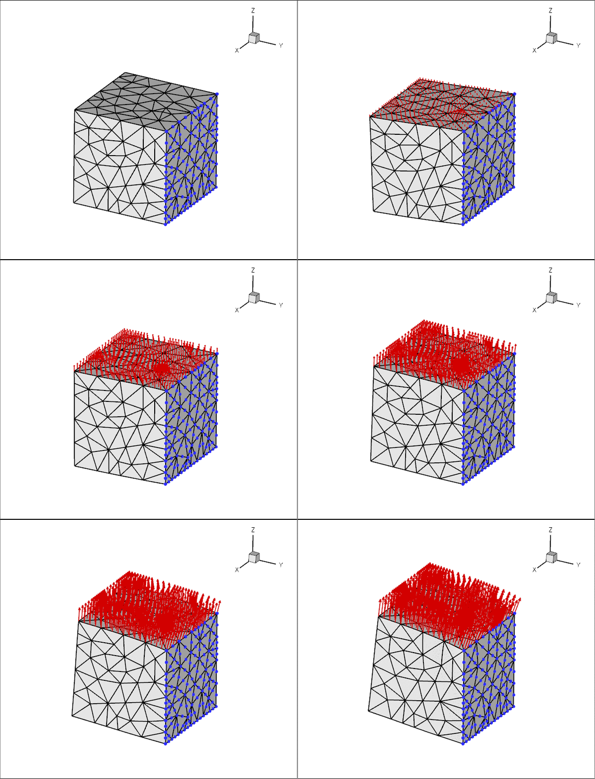
Plot of the deformation of a hollow 3D cube.

An alternative three-dimensional problem: the deformation of a bifurcating tube is described here.


Source files for this tutorial


PDF file

A pdf version of this document is available.