Demo problem: Free, small-amplitude axisymmetric oscillation of 2D circular disk

In this tutorial we demonstrate how to solve time-dependent solid mechanics problems. We consider the small-amplitude oscillations of a circular disk and compare the computed solution against analytical predictions based on linear elasticity.


Theory

Small-amplitude, axisymmetric oscillations of a circular disk of radius $ a $ are governed by the Navier-Lame equations

\[ (\lambda +2 \mu) \ \mbox{grad}^* \mbox{div}^* {\bf u}^* = \rho \frac{\partial^2 {\bf u}^*}{\partial t^{*2}}, \]

where the displacement field is given by $ {\bf u}^* = u^*(r^*,t^*) \ {\bf e}_r$. Here $ \lambda, \mu $ are the disk's two Lame constants and $ \rho $ is its density. The outer boundary is stress-free so that

\[ \tau_{rr} = \lambda \ \mbox{div}^* {\bf u}^* + 2 \mu \frac{\partial u^*}{\partial r^*} = 0 \ \ \ \ \ \mbox{at } r^* = a. \]

We non-dimensionalise all lengths and displacements on the disk's undeformed radius, $ {\cal L} = a $, and scale time on

\[ {\cal T} = a \sqrt{\frac{\rho}{(\lambda+2\mu)}}. \ \ \ \ \ \ \ \ \ \ \ \ \ \ \ \ \ \ \ \ \ (1) \]

This transforms the governing PDE into the dimensionless and parameter-free form

\[ \frac{\partial}{\partial r}\left(\frac{1}{r} \frac{\partial (ru)}{\partial r}\right) = \frac{\partial^2 u}{\partial t^2}, \]

subject to the boundary condition

\[ \frac{\nu}{1-2\nu}\frac{1}{r} \frac{\partial (ru)}{\partial r} + \frac{\partial u}{\partial r} = 0 \mbox{\ \ \ \ \ at } r=1, \]

where $ \nu $ is Poisson's ratio.

Making the ansatz $ u(r,t) = U(r) \sin(\omega t)$ transforms the PDE into an ODE for $ U(r) $:

\[ \frac{d}{dr}\left( \frac{1}{r} \frac{d(rU)}{d r}\right) + \omega^2 U = 0. \]

The solution of this ODE are Bessel functions and the requirement that $ U(r) $ is finite at $ r=0 $ implies that

\[ U(r) \sim J_1(\omega r). \]

where $ J_1 $ is the Bessel function of first order.

Substituting this into the stress-free boundary condition yields the dispersion relation

\[ \frac{\nu}{1-2\nu}\frac{1}{r} \frac{d (rJ_1(\omega r))}{d r} + \frac{dJ_1(\omega r)}{dr} = 0 \mbox{\ \ \ \ \ at } r=1, \]

for the eigenfrequencies $ \omega $.

If the disk performs oscillations in a single mode with eigenfrequency $ \omega $ its displacement field is therefore given by

\[ u(r,t) = A \ J_1(\omega r) \ \sin(\omega t), \]

where $ A $ is the (small) amplitude of the oscillations.


Implementation

We discretise the disk with oomph-lib's large-displacement solid mechanics elements and apply initial conditions that are consistent with an oscillation in its first eigenmode. As discussed in the Solid Mechanics Theory Tutorial, time-dependent problems require the specification of the (square of the) parameter

\[ \Lambda = \frac{{\cal L}}{{\cal T}} \sqrt{\frac{\rho}{{\cal S}}} \]

which represents the ratio of the system's intrinsic timescale $ {\cal L} \sqrt{\rho/{\cal S}} $, to the timescale $ {\cal T} $ used to non-dimensionalise time; here ${\cal S}$ is the reference stiffness used to non-dimensionalise the stresses.

Since the disk performs small-amplitude oscillations it is appropriate to assume linear elastic behaviour with Young's modulus $ E $ and Poisson's ratio $ \nu $. We therefore use Young's modulus to non-dimensionalise the stresses by setting $ {\cal S} = E. $ Using (1), the parameter $ \Lambda^2 $ is then given by

\[ \Lambda^2 = \frac{(1-\nu)}{(1+\nu)(1-2\nu)} \]

where we used the identity $ E = \mu(3\lambda +2 \mu)/(\lambda+\mu). $


Results

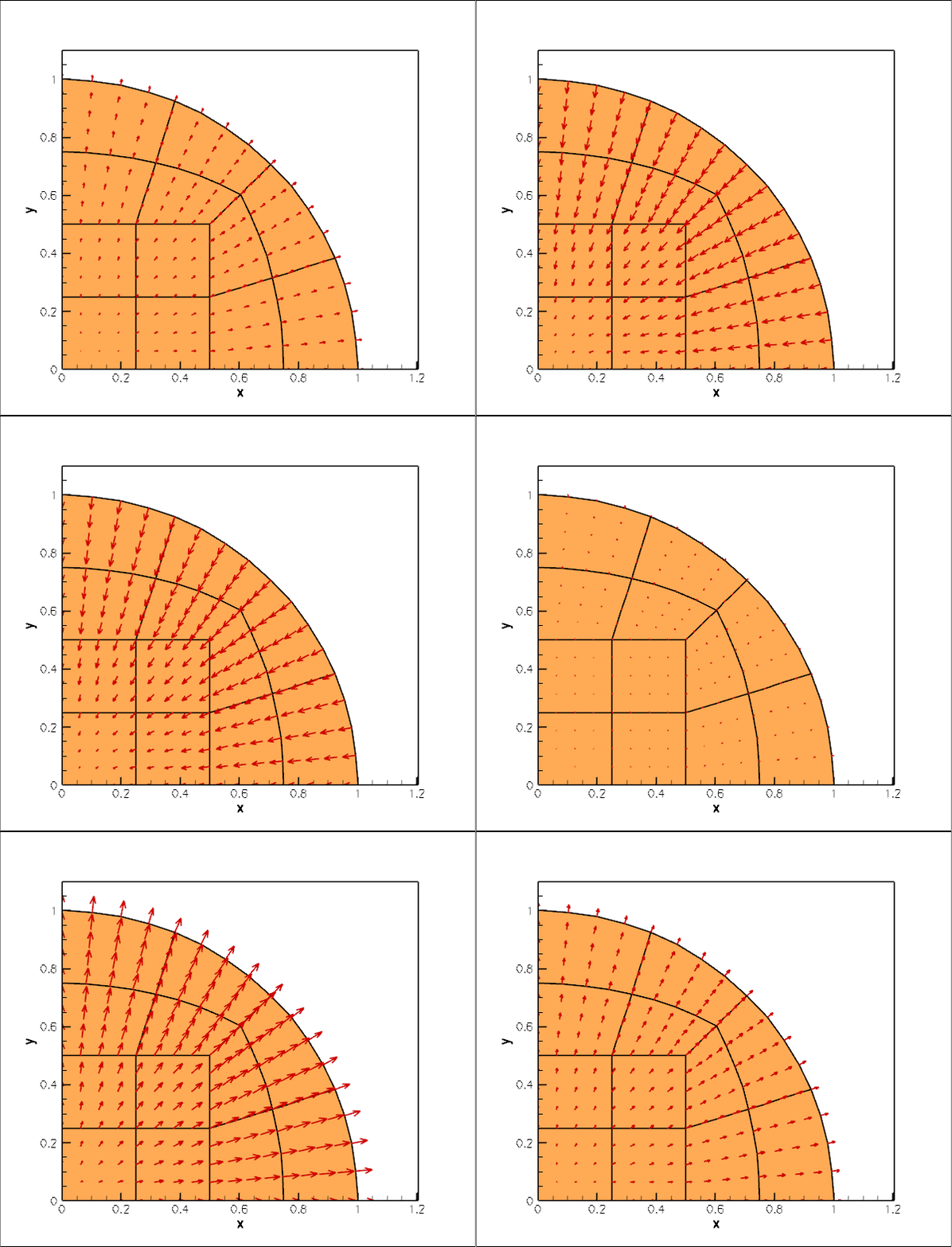
Here is an animation of the computed time-dependent displacement field. (Computations were only performed in a quarter of the domain, using appropriate symmetry boundary conditions along the lines $ x=0 $ and $ y=0. $

Animation of the displacement field.

The figure below shows (in red) the radius of a control point on the disk's curvilinear boundary. The green line shows the corresponding theoretical prediction for disk's radius for the first eigenfrequency $ \omega = 2.126. $ Theoretical and computational results are in excellent agreement.
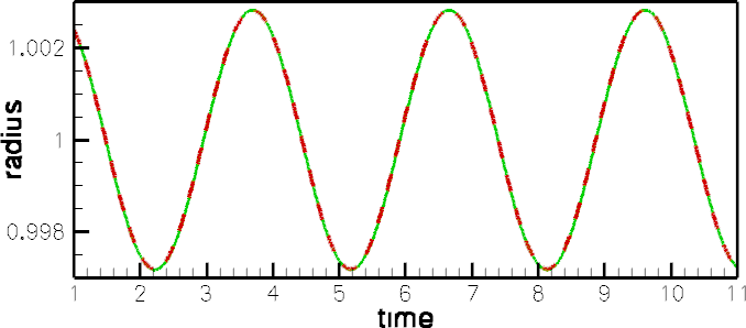
Time trace of the radius. Red: FE. Green: Linearised theory.

The final plot shows an animation of the theoretical and computed radial displacement fields along the line $ y=0 $, parametrised by a Lagrangian coordinate $ \xi $. The results are again in excellent agreement throughout the domain.
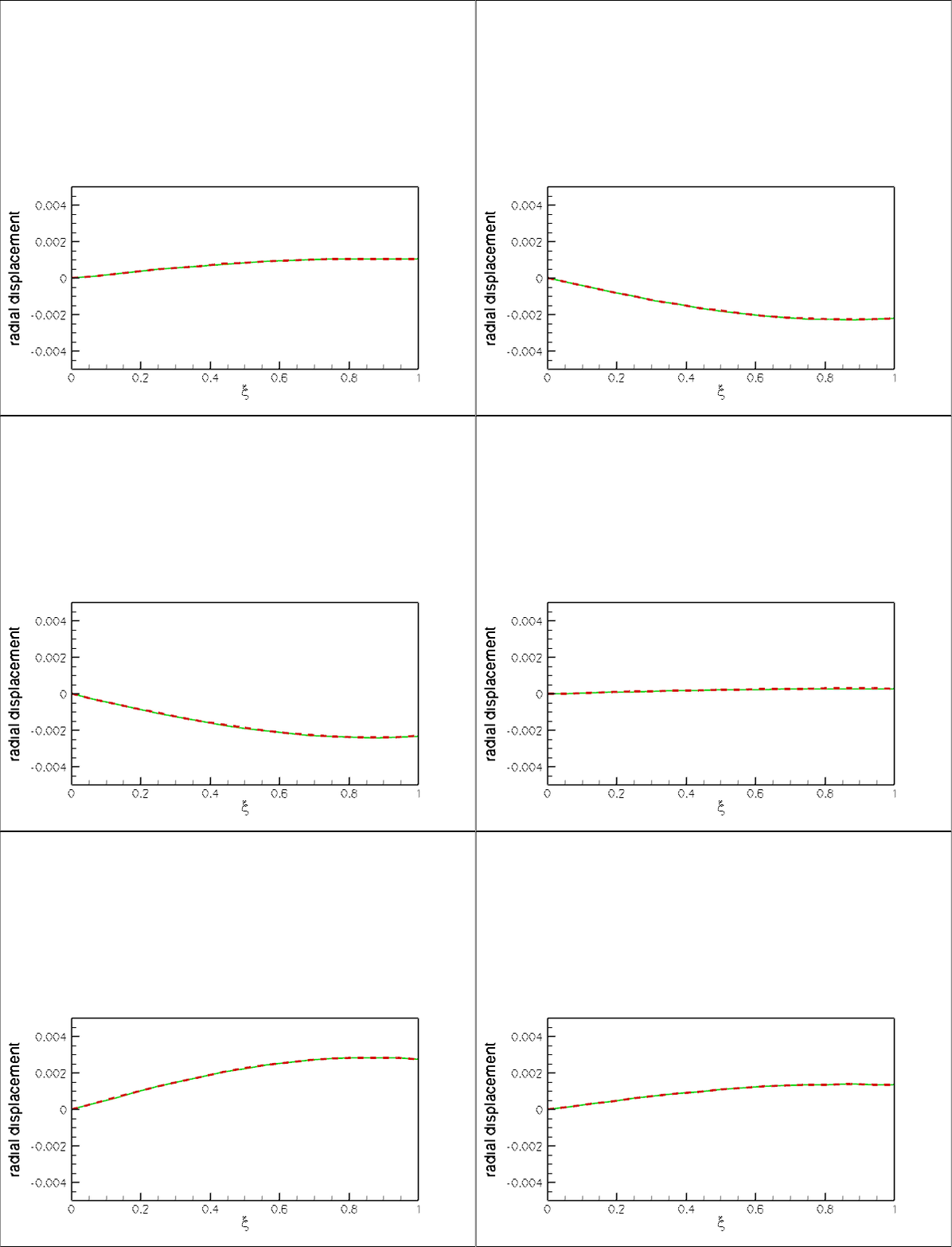
Animation of the exact (linearised) and computed radial displacement field.


Global parameters

As usual we define the global problem parameters in a namespace. We define Poisson's ratio, compute the associated timescale ratio $ \Lambda^2 $, and provide a pointer to the constitutive law.

The multiplier(...) function is needed during the assignment of the initial conditions. It is used to specify the product of the timescale ratio $ \Lambda^2 $ and the isotropic growth $ \Gamma $. Since the present problem does not involve any growth we have $ \Gamma = 1 $, so the function simply returns the (spatially constant) timescale ratio. See the Solid Mechanics Theory Tutorial and section Assignment of history values for the Newmark timestepper for further details.

//=======start_namespace==========================================
/// Global variables
//================================================================
{
/// Poisson's ratio
double Nu=0.3;
/// Timescale ratio
double Lambda_sq=(1.0-Nu)/((1.0+Nu)*(1.0-2.0*Nu));
/// Pointer to constitutive law
ConstitutiveLaw* Constitutive_law_pt=0;
/// Multiplier for inertia terms (needed for consistent assignment
/// of initial conditions in Newmark scheme)
double multiplier(const Vector<double>& xi)
{
}
} // end namespace
//////////////////////////////////////////////////////////////////// ////////////////////////////////...
double multiplier(const Vector< double > &xi)
Multiplier for inertia terms (needed for consistent assignment of initial conditions in Newmark schem...
ConstitutiveLaw * Constitutive_law_pt
Pointer to constitutive law.
double Nu
Poisson's ratio.
double Lambda_sq
Timescale ratio.


The driver code

We use command line arguments to indicate if the time-dependent simulation is run in validation mode, in which case we only perform a few timesteps:

//========start_main====================================================
/// Driver for disk oscillation problem
//======================================================================
int main(int argc, char* argv[])
{
// Store command line arguments
CommandLineArgs::setup(argc,argv);
// If there's a command line argument run the validation (i.e. do only
// 10 timesteps); otherwise do a few cycles
unsigned nstep=1000;
if (CommandLineArgs::Argc!=1)
{
nstep=10;
}
int main(int argc, char *argv[])
Driver for disk oscillation problem.

We create a Hookean constitutive equation, build the problem and run the simulation:

// Hookean constitutive equations
new GeneralisedHookean(&Global_Physical_Variables::Nu);
//Set up the problem
//Run the simulation
problem.run(nstep);
} // end of main
////////////////////////////////////////////////////////////////////// //////////////////////////////...
void run(const unsigned &nstep)
Run the problem: Pass number of timesteps to be performed.


Specifying the initial condition via a time-dependent GeomObject

The equations of solid mechanics require the assignment of initial conditions for the position and the velocity of all material particles at some initial time. Within oomph-lib, such initial conditions are most naturally specified in the form of time-dependent GeomObjects. Here is the specification of an axisymmetric, oscillating disk of unit radius whose displacement field is given by the analytical solution derived in the Theory section. The analytical solution requires the specification of the amplitude of the oscillation and the Poisson's ratio – these suffice to compute the time-dependent position, velocity and acceleration as a function of the current time, specified by the TimeStepper object.

//================disk_as_geom_object======================================
/// Axisymmetrially oscillating disk with displacement
/// field according to linear elasticity.
//=========================================================================
class AxisymOscillatingDisk : public GeomObject
{
public:
/// Constructor: 2 Lagrangian coordinate, 2 Eulerian coords. Pass
/// amplitude of oscillation, Poisson ratio nu, and pointer to
/// global timestepper.
AxisymOscillatingDisk(const double& ampl, const double& nu,
TimeStepper* time_stepper_pt);
/// Destructor (empty)
/// Position vector at Lagrangian coordinate xi at present
/// time
void position(const Vector<double>& xi, Vector<double>& r) const;
/// Parametrised velocity on object at current time: veloc = d r(xi)/dt.
void veloc(const Vector<double>& xi, Vector<double>& veloc);
/// Parametrised acceleration on object at current time:
/// accel = d^2 r(xi)/dt^2.
void accel(const Vector<double>& xi, Vector<double>& accel);
////////////////////////////////////////////////////////////////////
AxisymOscillatingDisk(const double &ampl, const double &nu, TimeStepper *time_stepper_pt)
Constructor: 2 Lagrangian coordinate, 2 Eulerian coords. Pass amplitude of oscillation,...
void veloc(const Vector< double > &xi, Vector< double > &veloc)
Parametrised velocity on object at current time: veloc = d r(xi)/dt.
void accel(const Vector< double > &xi, Vector< double > &accel)
Parametrised acceleration on object at current time: accel = d^2 r(xi)/dt^2.
void position(const Vector< double > &xi, Vector< double > &r) const
Position vector at Lagrangian coordinate xi at present time.
~AxisymOscillatingDisk()
Destructor (empty)

The class provides a static member function residual_for_dispersion(...) which is used to solve the nonlinear dispersion relation for the disk's eigenfrequency $ \omega $. The function is static (and thus essentially a global function) because it interacts with oomph-lib's black-box Newton solver.

/// Parametrised j-th time-derivative on object at current time:
/// \f$ \frac{d^{j} r(\zeta)}{dt^j} \f$.
void dposition_dt(const Vector<double>& xi, const unsigned& j,
Vector<double>& drdt)
{
switch (j)
{
// Current position
case 0:
position(xi,drdt);
break;
// Velocity:
case 1:
veloc(xi,drdt);
break;
// Acceleration:
case 2:
accel(xi,drdt);
break;
default:
std::ostringstream error_message;
error_message << j << "th derivative not implemented\n";
throw OomphLibError(error_message.str(),
OOMPH_CURRENT_FUNCTION,
OOMPH_EXCEPTION_LOCATION);
}
}
/// Residual of dispersion relation for use in black-box Newton method
/// which requires global (or static) functions.
/// Poisson's ratio is passed as parameter.
static void residual_for_dispersion(const Vector<double>& param,
const Vector<double>& omega,
Vector<double>& residual);

The private member data stores the amplitude and period of the oscillation, the material's Poisson ratio and the eigenfrequency.

private:
/// Amplitude of oscillation
double Ampl;
/// Period of oscillation
double T;
/// Poisson ratio nu
double Nu;
/// Eigenfrequency
double Omega;
}; // end disk_as_geom_object

Constructor

The constructor uses oomph-lib's black-box Newton solver, defined in the namespace BlackBoxFDNewtonSolver, to determine the eigenfrequency.

//==============ic_constructor============================================
/// Constructor: 2 Lagrangian coordinates, 2 Eulerian coords. Pass
/// amplitude of oscillation, Poisson ratio nu, and pointer to
/// global timestepper.
//========================================================================
const double& nu,
TimeStepper* time_stepper_pt) :
GeomObject(2,2,time_stepper_pt), Ampl(ampl), Nu(nu)
{
// Parameters for dispersion relation
Vector<double> param(1);
param[0]=Nu;
// Initial guess for eigenfrequency
Vector<double> omega(1);
omega[0]=2.0;
// Find eigenfrequency from black box Newton solver
BlackBoxFDNewtonSolver::black_box_fd_newton_solve(residual_for_dispersion,
param,omega);
// Assign eigenfrequency
Omega=omega[0];
// Assign/doc period of oscillation
T=2.0*MathematicalConstants::Pi/Omega;
std::cout << "Period of oscillation: " << T << std::endl;
}

The dispersion relation

Here is the specification of the dispersion relation, in the form required by oomph-lib's black-box Newton solver. The Bessel functions are computed by C.R. Bond's bessjy01a(...) function, available (with permission) via oomph-lib's CRBond_Bessel namespace.

//======================start_of_dispersion===============================
/// Residual of dispersion relation for use in black box Newton method
/// which requires global (or static) functions.
/// Poisson's ratio is passed as parameter.
//========================================================================
const Vector<double>& param, const Vector<double>& omega,
Vector<double>& residual)
{
// Extract parameters
double nu=param[0];
// Argument of various Bessel functions
double arg=omega[0];
// Bessel fcts J_0(x), J_1(x), Y_0(x), Y_1(x) and their derivatives
double j0,j1,y0,y1,j0p,j1p,y0p,y1p;
CRBond_Bessel::bessjy01a(arg,j0,j1,y0,y1,j0p,j1p,y0p,y1p);
// Residual of dispersion relation
residual[0]=nu/(1.0-2.0*nu)*(j1+(j0-j1/omega[0])*omega[0])+
(j0-j1/omega[0])*omega[0];
}
static void residual_for_dispersion(const Vector< double > &param, const Vector< double > &omega, Vector< double > &residual)
Residual of dispersion relation for use in black-box Newton method which requires global (or static) ...

The position(...), veloc(...) and accel(...) functions

The position(...), veloc(...) and accel(...) functions specify the motion of the GeomObject, according to the solution of the linearised equations derived in the Theory section. Here is a listing of the position(...) function:

//===============start_position===========================================
/// Position Vector at Lagrangian coordinate xi at present
/// time
//========================================================================
void AxisymOscillatingDisk::position(const Vector<double>& xi,
Vector<double>& r) const
{
// Parameter values at present time
double time=Geom_object_time_stepper_pt->time_pt()->time();
// Radius in Lagrangian coordinates
double lagr_radius=sqrt( pow(xi[0],2) + pow(xi[1],2) );
if (lagr_radius<1.0e-12)
{
// Position Vector
r[0]=0.0;
r[1]=0.0;
}
else
{
// Bessel fcts J_0(x), J_1(x), Y_0(x), Y_1(x) and their derivatives
double j0,j1,y0,y1,j0p,j1p,y0p,y1p;
CRBond_Bessel::bessjy01a(Omega*lagr_radius,j0,j1,y0,y1,j0p,j1p,y0p,y1p);
// Displacement field
double u=Ampl*j1*sin(2.0*MathematicalConstants::Pi*time/T);
// Position Vector
r[0]=(xi[0]+xi[0]/lagr_radius*u);
r[1]=(xi[1]+xi[1]/lagr_radius*u);
}
} //end position
double T
Period of oscillation.
double Ampl
Amplitude of oscillation.
double Omega
Eigenfrequency.

The veloc(...) and accel(...) functions are very similar and we omit their listings in the interest of brevity. See the source code disk_oscillation.cc for details.


The mesh

We discretise a quarter of the domain with a solid mechanics version of the refineable quarter circle sector mesh, constructed using multiple inheritance.

//======================start_mesh================================
/// Elastic quarter circle sector mesh: We "upgrade"
/// the RefineableQuarterCircleSectorMesh to become an
/// SolidMesh and equate the Eulerian and Lagrangian coordinates,
/// thus making the domain represented by the mesh the stress-free
/// configuration.
//================================================================
template <class ELEMENT>
public virtual RefineableQuarterCircleSectorMesh<ELEMENT>,
public virtual SolidMesh
{
//////////////////////////////////////////////////////////////////// ////////////////////////////////...

The constructor calls the constructor of the underlying non-solid mesh, checks that the element type, specified by the template argument, is a SolidFiniteElement, and sets the Lagrangian coordinates of all nodes to their Eulerian positions, making the current configuration stress-free.

public:
/// Constructor: Build mesh and copy Eulerian coords to Lagrangian
/// ones so that the initial configuration is the stress-free one.
const double& xi_lo,
const double& fract_mid,
const double& xi_hi,
TimeStepper* time_stepper_pt=
&Mesh::Default_TimeStepper) :
RefineableQuarterCircleSectorMesh<ELEMENT>(wall_pt,xi_lo,fract_mid,xi_hi,
time_stepper_pt)
{
#ifdef PARANOID
/// Check that the element type is derived from the SolidFiniteElement
SolidFiniteElement* el_pt=dynamic_cast<SolidFiniteElement*>
(finite_element_pt(0));
if (el_pt==0)
{
throw OomphLibError(
"Element needs to be derived from SolidFiniteElement\n",
OOMPH_CURRENT_FUNCTION,
OOMPH_EXCEPTION_LOCATION);
}
#endif
// Make the current configuration the undeformed one by
// setting the nodal Lagrangian coordinates to their current
// Eulerian ones
set_lagrangian_nodal_coordinates();
}
};


The Problem class

The Problem class has the usual member functions which will be discussed in more detail below.

//========start_class===================================================
/// Problem class to simulate small-amplitude oscillations of
/// a circular disk.
//======================================================================
template<class ELEMENT>
class DiskOscillationProblem : public Problem
{
public:
/// Constructor
/// Update function (empty)
/// Access function for the solid mesh
{
Problem::mesh_pt());
}
/// Run the problem: Pass number of timesteps to be performed.
void run(const unsigned& nstep);
/// Doc the solution
void doc_solution(DocInfo& doc_info);
private:
/// Trace file
ofstream Trace_file;
/// Vector of pointers to nodes whose position we're tracing
Vector<Node*> Trace_node_pt;
/// Geometric object that specifies the initial conditions
}; // end class
Vector< Node * > Trace_node_pt
Vector of pointers to nodes whose position we're tracing.
AxisymOscillatingDisk * IC_geom_object_pt
Geometric object that specifies the initial conditions.
ofstream Trace_file
Trace file.
DiskOscillationProblem()
Constructor.
void actions_after_newton_solve()
Update function (empty)
ElasticRefineableQuarterCircleSectorMesh< ELEMENT > * mesh_pt()
Access function for the solid mesh.
void doc_solution(DocInfo &doc_info)
Doc the solution.
void actions_before_newton_solve()
Update function (empty)


The Problem constructor

We start by creating the timestepper – the standard Newmark timestepper with two history values (We refer to another tutorial for a discussion of the template parameter in the Newmark timestepper). Next, we create a GeomObject that specifies the curvilinear boundary of the quarter circle domain and pass it to the mesh constructor.

//============start_constructor=========================================
/// Constructor
//======================================================================
template<class ELEMENT>
{
// Allocate the timestepper: The classical Newmark scheme with
// two history values.
add_time_stepper_pt(new Newmark<2>);
// GeomObject that specifies the curvilinear boundary of the
// circular disk
GeomObject* curved_boundary_pt=new Ellipse(1.0,1.0);
//The start and end intrinsic coordinates on the geometric object
// that defines the curvilinear boundary of the disk
double xi_lo=0.0;
double xi_hi=2.0*atan(1.0);
// Fraction along geometric object at which the radial dividing line
// is placed
double fract_mid=0.5;
//Now create the mesh
curved_boundary_pt,xi_lo,fract_mid,xi_hi,time_stepper_pt());

We select the nodes on the horizontal symmetry boundary and on the curvilinear boundary as control nodes whose displacement we shall document in a trace file.

// Setup trace nodes as the nodes on boundaries 0 (= horizontal symmetry
// boundary) and 1 (=curved boundary)
unsigned nnod0=mesh_pt()->nboundary_node(0);
unsigned nnod1=mesh_pt()->nboundary_node(1);
Trace_node_pt.resize(nnod0+nnod1);
for (unsigned j=0;j<nnod0;j++)
{
Trace_node_pt[j]=mesh_pt()->boundary_node_pt(0,j);
}
for (unsigned j=0;j<nnod1;j++)
{
Trace_node_pt[j+nnod0]=mesh_pt()->boundary_node_pt(1,j);
} //done choosing trace nodes

We apply symmetry boundary conditions along the horizontal and vertical symmetry boundaries: zero vertical displacement along the line $ y=0 $ (boundary 0) and zero horizontal displacement along the line $ x=0 $ (boundary 2).

// Pin the horizontal boundary in the vertical direction
unsigned n_hor = mesh_pt()->nboundary_node(0);
for(unsigned i=0;i<n_hor;i++)
{
mesh_pt()->boundary_node_pt(0,i)->pin_position(1);
}
// Pin the vertical boundary in the horizontal direction
unsigned n_vert = mesh_pt()->nboundary_node(2);
for(unsigned i=0;i<n_vert;i++)
{
mesh_pt()->boundary_node_pt(2,i)->pin_position(0);
} // done bcs

We complete the build of the elements by specifying the pointer to the constitutive law and to the timescale ratio $ \Lambda^2. $

//Finish build of elements
unsigned n_element =mesh_pt()->nelement();
for(unsigned i=0;i<n_element;i++)
{
//Cast to a solid element
ELEMENT *el_pt = dynamic_cast<ELEMENT*>(mesh_pt()->element_pt(i));
//Set the constitutive law
el_pt->constitutive_law_pt() =
// Set the timescale ratio
el_pt->lambda_sq_pt()=&Global_Physical_Variables::Lambda_sq;
}

Finally, we apply one level of uniform refinement and assign the equation numbers.

// Refine uniformly
mesh_pt()->refine_uniformly();
// Assign equation numbers
assign_eqn_numbers();
} // end constructor


Post-processing

We start the post-processing routine by plotting the shape of the deformed body, before documenting the radii of the control points and the exact outer radius of the disk (according to linear theory) in the trace file.

//=====================start_doc====================================
/// Doc the solution
//==================================================================
template<class ELEMENT>
DocInfo& doc_info)
{
ofstream some_file, some_file2;
char filename[100];
// Number of plot points
unsigned npts;
npts=5;
// Output shape of deformed body
//------------------------------
sprintf(filename,"%s/soln%i.dat",doc_info.directory().c_str(),
doc_info.number());
some_file.open(filename);
mesh_pt()->output(some_file,npts);
some_file.close();
// Write trace file
//-----------------
// Get position on IC object (exact solution)
Vector<double> r_exact(2);
Vector<double> xi(2);
xi[0]=1.0;
xi[1]=0.0;
IC_geom_object_pt->position(xi,r_exact);
// Exact outer radius for linear elasticity
double exact_r=r_exact[0];
// Add to trace file
Trace_file << time_pt()->time() << " "
<< exact_r << " ";
// Doc radii of control nodes
unsigned ntrace_node=Trace_node_pt.size();
for (unsigned j=0;j<ntrace_node;j++)
{
Trace_file << sqrt(pow(Trace_node_pt[j]->x(0),2)+
pow(Trace_node_pt[j]->x(1),2)) << " ";
}
Trace_file << std::endl;

Next we and output the exact and computed displacements and velocities (as a function of the Lagrangian coordinate) along the horizontal symmetry line where $ y=0. $ The displacements are given by the difference between the current Eulerian and the Lagrangian positions:

// Get displacement as a function of the radial coordinate
//--------------------------------------------------------
// along boundary 0
//-----------------
{
// Number of elements along boundary 0:
unsigned nelem=mesh_pt()->nboundary_element(0);
// Open files
sprintf(filename,"%s/displ_along_line%i.dat",doc_info.directory().c_str(),
doc_info.number());
some_file.open(filename);
ofstream some_file2;
sprintf(filename,"%s/exact_displ_along_line%i.dat",
doc_info.directory().c_str(),
doc_info.number());
some_file2.open(filename);
Vector<double> s(2);
Vector<double> x(2);
Vector<double> dxdt(2);
Vector<double> xi(2);
Vector<double> r_exact(2);
Vector<double> v_exact(2);
for (unsigned e=0;e<nelem;e++)
{
some_file << "ZONE " << std::endl;
some_file2 << "ZONE " << std::endl;
for (unsigned i=0;i<npts;i++)
{
// Move along bottom edge of element
s[0]=-1.0+2.0*double(i)/double(npts-1);
s[1]=-1.0;
// Get pointer to element
SolidFiniteElement* el_pt=dynamic_cast<SolidFiniteElement*>
(mesh_pt()->boundary_element_pt(0,e));
// Get Lagrangian coordinate
el_pt->interpolated_xi(s,xi);
// Get Eulerian coordinate
el_pt->interpolated_x(s,x);
// Get velocity
el_pt->interpolated_dxdt(s,1,dxdt);
// Get exact Eulerian position
IC_geom_object_pt->position(xi,r_exact);
// Get exact velocity
IC_geom_object_pt->veloc(xi,v_exact);
// Plot radial distance and displacement
some_file << xi[0] << " " << x[0]-xi[0] << " "
<< dxdt[0] << std::endl;
some_file2 << xi[0] << " " << r_exact[0]-xi[0] << " "
<< v_exact[0] << std::endl;
}
}
some_file.close();
some_file2.close();
} // end line output

The function also contains similar output for 2D displacements fields but we suppress the listing here and refer to the source code disk_oscillation.cc for details.


Running the time-integration

Before starting the time-integration we create an output directory and open a trace file that we shall use to record the displacements of the control points selected earlier.

//=====================start_run====================================
/// Run the problem: Pass number of timesteps to be performed.
//==================================================================
template<class ELEMENT>
void DiskOscillationProblem<ELEMENT>::run(const unsigned& nstep)
{
// Output
DocInfo doc_info;
// Output directory
doc_info.set_directory("RESLT");
// Open trace file
char filename[100];
sprintf(filename,"%s/trace.dat",doc_info.directory().c_str());
Trace_file.open(filename);

Next, we initialise the global Time object so that the initial condition is assigned at $ t= 1 $, and set the timestep for the time integration.

// Initialise time
double time0=1.0;
time_pt()->time()=time0;
// Set timestep
double dt=0.01;
time_pt()->initialise_dt(dt);

We choose the amplitude of the oscillation and pass it and the value of Poisson's ratio to the constructor of the GeomObject that specifies the initial condition.

// Create geometric object that specifies the initial conditions:
// Amplitude of the oscillation
double ampl=0.005;
// Build the GeomObject
IC_geom_object_pt=new AxisymOscillatingDisk(ampl,
time_stepper_pt());

To assign the initial conditions, we create a SolidInitialCondition object from the GeomObject and call the helper function set_newmark_initial_condition_consistently(...) which assigns the (Newmark) history values of the nodal positions to be consistent with the current motion of the AxisymOscillationDisk.

// Turn into object that specifies the initial conditions:
SolidInitialCondition* IC_pt = new SolidInitialCondition(IC_geom_object_pt);
// Assign initial condition
SolidMesh::Solid_IC_problem.set_newmark_initial_condition_consistently(
this,mesh_pt(),time_stepper_pt(),IC_pt,dt,

Finally, we document the initial condition and start the timestepping loop.

// Doc initial state
doc_solution(doc_info);
doc_info.number()++;
//Timestepping loop
for(unsigned i=0;i<nstep;i++)
{
unsteady_newton_solve(dt);
doc_solution(doc_info);
doc_info.number()++;
}
} // end of run


Comments and Exercises

Higher modes

In the constructor of the AxisymOscillationDisk we used an initial guess of $ \omega=2 $ for the eigenfrequency. With this initial guess the Newton iteration converges to the first eigenfrequency with a period of $ T=2.96. $ The first eigenmode is relatively smooth and therefore easily resolved on a coarse mesh. Explore the system's higher eigenmodes by specifying larger initial guesses for $ \omega $. For instance, specifying an initial guess of $ \omega=4 $ the Newton iteration converges to an eigenmode with a period of $ 0.297. $ You will need much finer meshes and smaller timesteps to accurately resolve these oscillations. This is because the Newmark scheme does not have any dissipation. This implies that any spurious features that are generated by under-resolved computations persist indefinitely.

Assignment of history values for the Newmark timestepper

We commented elsewhere that, even though the mathematical initial value problem only requires the specification of the initial position and the velocity, the Newmark timestepper requires assignments for the initial positions and for two history values, representing the discrete velocities and accelerations. We refer to the relevant section in the Solid Mechanics Tutorial for a discussion of the automatic assignment of these history values for solid mechanics problems.

We note that the function SolidMesh::Solid_IC_problem.set_newmark_initial_condition_consistently(...) which may be used to assign the history values, requires the specification of the product of the (possibly spatially-varying) "multiplier" $\Gamma \Lambda^2 $ – the product of the growth factor and the timescale ratio – via a function pointer. If this function pointer is not specified, it is assumed that the product of these two quantities is equal to one – appropriate for a case without growth and when time is non-dimensionalised on the system's intrinsic timescale.

If the "multiplier" is not (or wrongly) specified, the assignment of the history values will be incorrect and oomph-lib will issue a suitable warning if the library is compiled with the PARANOID flag. You should experiment with this by removing the function pointer in the call to SolidMesh::Solid_IC_problem.set_newmark_initial_condition_consistently(...).


Source files for this tutorial


PDF file

A pdf version of this document is available.