Demo problem: Solid Mechanics using unstructured meshes with adaptivity

The purpose of this tutorial is to demonstrate the adaptive solution of solid mechanics problems using unstructured meshes generated by oomph-lib's inline unstructured mesh generation procedures. The use of these methods for solid mechanics problems required no additional effort on the part of the user and the setup is essentially the same as that described for unstructured solid mechanics without mesh adaptation. Lagrangian coordinates are projected between meshes in the same way as all other field variables, Eulerian coordinates and history values, see the description in another tutorial.

The solid mechanics problem described here can be regarded as a sub-problem for the
unstructured adaptive fluid–structure interaction tutorial. In addition, we can use the problem to assess the errors incurred when projecting the solution between different meshes.


The problem

An elastic bar is fixed at the base and loaded by a constant pressure on its left-hand side. The pressure load is increased and then decreased so that at the end of the simulation the bar should return to its undeformed position. The strain energy in the final configuration is a measure of the projection error because if there were no projection at all it would be exactly zero (or certainly zero to less than machine precision).
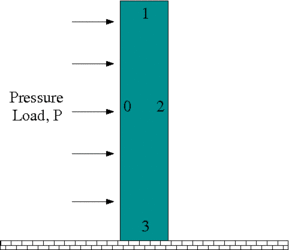
Sketch of the problem.


Results

The animation shown below illustrates the solid's deformation and illustrates the adaptation of the mesh as the load changes.
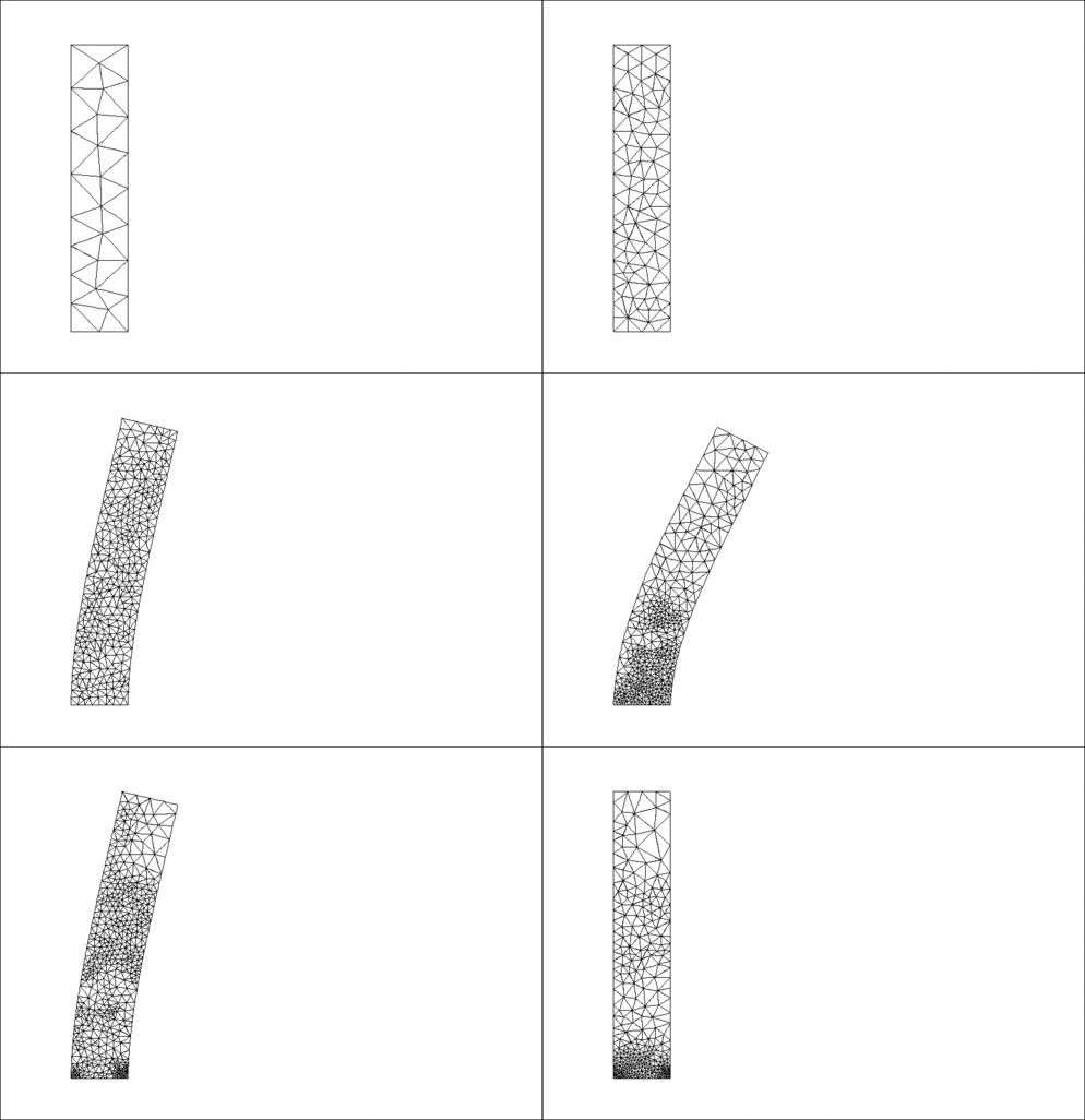
Plot of the deformation.

The initial strain energy is $ O(10^{-28}) $, and the strain energy in the final configuration after the external pressure has been reset to zero, but the mesh has been adapted, is $ O(10^{-8}) $. The strain energy at the maximum deflection is $ O(10^{-3}) $.


Global Physical Variables

We define the various physical variables in a global namespace. We define Poisson's ratio and prepare a pointer to a constitutive equation.

//=======start_namespace==========================================
/// Global variables
//================================================================
{
/// Poisson's ratio
double Nu=0.3;
/// Pointer to constitutive law
ConstitutiveLaw* Constitutive_law_pt=0;
//////////////////////////////////////////////////////////////////// ////////////////////////////////...
ConstitutiveLaw * Constitutive_law_pt
Pointer to constitutive law.

Next we define the pressure load to be applied at the left-hand boundary,

/// Uniform pressure
double P = 0.0;
/// Constant pressure load. The arguments to this function are imposed
/// on us by the SolidTractionElements which allow the traction to
/// depend on the Lagrangian and Eulerian coordinates x and xi, and on the
/// outer unit normal to the surface. Here we only need the outer unit
/// normal.
void constant_pressure(const Vector<double> &xi, const Vector<double> &x,
const Vector<double> &n, Vector<double> &traction)
{
unsigned dim = traction.size();
for(unsigned i=0;i<dim;i++)
{
traction[i] = -P*n[i];
}
}
} //end namespace
void constant_pressure(const Vector< double > &xi, const Vector< double > &x, const Vector< double > &n, Vector< double > &traction)
Constant pressure load. The arguments to this function are imposed on us by the SolidTractionElements...


The driver code

The driver code consists of essentially the same code repeated for three different formulations of solid mechanics: (i) (compressible) displacement only; (ii) (compressible) displacement-pressure; and (iii) incompressible displacement-pressure. We shall describe the code only for the first formulation.

Initially, we specify an output directory and instantiate a constitutive equation. (Recall that the single-argument constructor to the GeneralisedHookean constitutive law implies that all stresses are non-dimensionalised on Young's modulus $ E $).

//===========start_main===================================================
/// Demonstrate how to solve an unstructured solid problem
//========================================================================
int main(int argc, char **argv)
{
//Doc info object
DocInfo doc_info;
// Output directory
doc_info.set_directory("RESLT");
// Create generalised Hookean constitutive equations
new GeneralisedHookean(&Global_Physical_Variables::Nu);
int main(int argc, char **argv)
Demonstrate how to solve an unstructured solid problem.

We then open an output file for the strain energy, create the Problem object using a displacement formulation of the equations and output the initial configuration.

{
std::ofstream strain("RESLT/s_energy.dat");
std::cout << "Running with pure displacement formulation\n";
//Set up the problem
//Output initial configuration
problem.doc_solution(doc_info);
doc_info.number()++;
Unstructured solid problem.
void doc_solution(DocInfo &doc_info)
Doc the solution.

Finally, we perform the parameter study by slowly increasing and then reducing the pressure on the left-hand boundary. Note that one round of mesh adaptation is specified for every Newton solve.

// Parameter study
double pressure_increment=0.1e-2;
unsigned nstep=5;
for (unsigned istep=0;istep<nstep;istep++)
{
// Solve the problem with one round of adaptivity
problem.newton_solve(1);
double strain_energy = problem.get_strain_energy();
std::cout << "Strain energy is " << strain_energy << "\n";
//Output strain energy to file
strain << Global_Physical_Variables::P << " " << strain_energy << std::endl;
//Output solution
problem.doc_solution(doc_info);
doc_info.number()++;
//Reverse direction of increment
if(istep==2) {pressure_increment *= -1.0;}
// Increase (or decrease) load
Global_Physical_Variables::P+=pressure_increment;
}
strain.close();
} //end_displacement_formulation
double get_strain_energy()
Calculate the strain energy.


The Problem class

The Problem class has the obvious member functions as well as a function to set whether the material is incompressible and a function to compute the strain energy of the elastic body. The class provides storage for the two sub-meshes: the bulk mesh of 2D solid elements and the mesh of 1D traction elements that will be attached to the left-hand boundary. In addition, storage is provided for the polygon that represents the initial outer boundary of the solid body and a boolean flag that is used to specify whether the material is incompressible or not.

//==============start_problem=========================================
/// Unstructured solid problem
//====================================================================
template<class ELEMENT>
class UnstructuredSolidProblem : public Problem
{
public:
/// Constructor:
/// Destructor (empty)
/// Set the problem to be incompressible
/// Doc the solution
void doc_solution(DocInfo& doc_info);
/// Calculate the strain energy
/// Remove Traction Mesh
/// Add on the traction elements after adaptation
private:
/// Bulk mesh
RefineableSolidTriangleMesh<ELEMENT>* Solid_mesh_pt;
/// Pointer to mesh of traction elements
SolidMesh* Traction_mesh_pt;
/// Triangle mesh polygon for outer boundary
TriangleMeshPolygon* Outer_boundary_polyline_pt;
/// Boolean flag used in an incompressible problem
};
~UnstructuredSolidProblem()
Destructor (empty)
TriangleMeshPolygon * Outer_boundary_polyline_pt
Triangle mesh polygon for outer boundary.
SolidMesh * Traction_mesh_pt
Pointer to mesh of traction elements.
void actions_before_adapt()
Remove Traction Mesh.
bool Incompressible
Boolean flag used in an incompressible problem.
void set_incompressible()
Set the problem to be incompressible.
void actions_after_adapt()
Add on the traction elements after adaptation.
RefineableSolidTriangleMesh< ELEMENT > * Solid_mesh_pt
Bulk mesh.


The Problem constructor

We begin by building the closed, piecewise linear boundary of the undeformed solid body $ x_{1} \in [0,1] $, $ x_{2} \in [0,5]. $ The boundaries are labelled anticlockwise with boundary with the left-hand boundary being boundary 0, see the sketch above. This process is a simplified version of the construction used in another tutorial.

//===============start_constructor========================================
/// Constructor for unstructured solid problem
//========================================================================
template<class ELEMENT>
Incompressible(false)
{
// Build the boundary segments for outer boundary, consisting of
//--------------------------------------------------------------
// four separeate polyline segments
//---------------------------------
Vector<TriangleMeshCurveSection*> boundary_segment_pt(4);
// Initialize boundary segment
Vector<Vector<double> > bound_seg(2);
for(unsigned i=0;i<2;i++) {bound_seg[i].resize(2);}
// First boundary segment
bound_seg[0][0]=0.0;
bound_seg[0][1]=0.0;
bound_seg[1][0]=0.0;
bound_seg[1][1]=5.0;
// Specify 1st boundary id
unsigned bound_id = 0;
// Build the 1st boundary segment
boundary_segment_pt[0] = new TriangleMeshPolyLine(bound_seg,bound_id);
// Second boundary segment
bound_seg[0][0]=0.0;
bound_seg[0][1]=5.0;
bound_seg[1][0]=1.0;
bound_seg[1][1]=5.0;
// Specify 2nd boundary id
bound_id = 1;
// Build the 2nd boundary segment
boundary_segment_pt[1] = new TriangleMeshPolyLine(bound_seg,bound_id);
// Third boundary segment
bound_seg[0][0]=1.0;
bound_seg[0][1]=5.0;
bound_seg[1][0]=1.0;
bound_seg[1][1]=0.0;
// Specify 3rd boundary id
bound_id = 2;
// Build the 3rd boundary segment
boundary_segment_pt[2] = new TriangleMeshPolyLine(bound_seg,bound_id);
// Fourth boundary segment
bound_seg[0][0]=1.0;
bound_seg[0][1]=0.0;
bound_seg[1][0]=0.0;
bound_seg[1][1]=0.0;
// Specify 4th boundary id
bound_id = 3;
// Build the 4th boundary segment
boundary_segment_pt[3] = new TriangleMeshPolyLine(bound_seg,bound_id);
// Create the triangle mesh polygon for outer boundary using boundary segment
Outer_boundary_polyline_pt = new TriangleMeshPolygon(boundary_segment_pt);
// There are no holes
//-------------------------------
// Now build the mesh, based on the boundaries specified by
//---------------------------------------------------------
// polygons just created
//----------------------
double uniform_element_area=0.2;
TriangleMeshClosedCurve* closed_curve_pt=Outer_boundary_polyline_pt;
// Use the TriangleMeshParameters object for gathering all
// the necessary arguments for the TriangleMesh object
TriangleMeshParameters triangle_mesh_parameters(
closed_curve_pt);
// Define the maximum element area
triangle_mesh_parameters.element_area() =
uniform_element_area;
// Create the mesh
Solid_mesh_pt =
new RefineableSolidTriangleMesh<ELEMENT>(
triangle_mesh_parameters);

We next construct an error estimator and specify the target errors and element sizes.

//hierher
// Disable the use of an iterative solver for the projection
// stage during mesh adaptation
Solid_mesh_pt->disable_iterative_solver_for_projection();
// Set error estimator for bulk mesh
Z2ErrorEstimator* error_estimator_pt=new Z2ErrorEstimator;
Solid_mesh_pt->spatial_error_estimator_pt()=error_estimator_pt;
// Set targets for spatial adaptivity
Solid_mesh_pt->max_permitted_error()=0.0001;
Solid_mesh_pt->min_permitted_error()=0.001;
Solid_mesh_pt->max_element_size()=0.2;
Solid_mesh_pt->min_element_size()=0.001;

We output the boundaries, construct an empty traction mesh and combine the bulk and traction meshes into a global mesh.

// Output mesh boundaries
this->Solid_mesh_pt->output_boundaries("boundaries.dat");
// Make the traction mesh
Traction_mesh_pt=new SolidMesh;
// Add sub meshes
add_sub_mesh(Solid_mesh_pt);
add_sub_mesh(Traction_mesh_pt);
// Build the global mesh
build_global_mesh();

Finally we call actions_after_adapt(), which constructs the traction elements, sets the boundary conditions and completes the build of the elements, and then we assign the equation numbers

//Call actions after adapt:
// 1) to build the traction elements
// 2) to pin the nodes on the lower boundary (boundary 3)
// 3) to complete the build of the elements
// Note there is slight duplication here because we rebuild the global mesh
// twice.
this->actions_after_adapt();
// Setup equation numbering scheme
cout <<"Number of equations: " << assign_eqn_numbers() << std::endl;
} //end constructor


Actions before adaptation

The actions_before_adapt() function simply deletes the traction elements and clears the storage in the face mesh.

//==============start_actions_before_adapt================================
/// Actions before adapt: remove the traction elements in the surface mesh
//========================================================================
template<class ELEMENT>
{
// How many surface elements are in the surface mesh
unsigned n_element = Traction_mesh_pt->nelement();
// Loop over the surface elements and kill them
for(unsigned e=0;e<n_element;e++) {delete Traction_mesh_pt->element_pt(e);}
// Wipe the mesh
Traction_mesh_pt->flush_element_and_node_storage();
} // end_actions_before_adapt


Actions before adaptation

The function actions_after_adapt() first builds the traction elements adjacent to the left-hand boundary (boundary 0) and rebuilds the global mesh. The constant_pressure() load function is passed to each of the traction elements.

//=================start_actions_after_adapt=============================
/// Need to add on the traction elements after adaptation
//=======================================================================
template<class ELEMENT>
{
//The boundary in question is boundary 0
unsigned b=0;
// How many bulk elements are adjacent to boundary b?
unsigned n_element = Solid_mesh_pt->nboundary_element(b);
// Loop over the bulk elements adjacent to boundary b
for(unsigned e=0;e<n_element;e++)
{
// Get pointer to the bulk element that is adjacent to boundary b
ELEMENT* bulk_elem_pt = dynamic_cast<ELEMENT*>(
Solid_mesh_pt->boundary_element_pt(b,e));
//Find the index of the face of element e along boundary b
int face_index = Solid_mesh_pt->face_index_at_boundary(b,e);
//Create solid traction element
SolidTractionElement<ELEMENT> *el_pt =
new SolidTractionElement<ELEMENT>(bulk_elem_pt,face_index);
// Add to mesh
Traction_mesh_pt->add_element_pt(el_pt);
//Set the traction function
}
//Now rebuild the global mesh
this->rebuild_global_mesh();

Next, the boundary conditions of a fixed base (boundary 3) are set. These must be reset every time after an adaptation because completely new nodes are generated.

//(Re)set the boundary conditions
//Pin both positions at lower boundary (boundary 3)
unsigned ibound=3;
unsigned num_nod= mesh_pt()->nboundary_node(ibound);
for (unsigned inod=0;inod<num_nod;inod++)
{
// Get node
SolidNode* nod_pt=Solid_mesh_pt->boundary_node_pt(ibound,inod);
// Pin both directions
for (unsigned i=0;i<2;i++) {nod_pt->pin_position(i);}
}
//End of set boundary conditions

Finally, the constitutive law and, if required, incompressibility flag are passed to the bulk (solid) elements. Again, this must be performed after every adaptation because a completely new mesh is generated.

// Complete the build of all elements so they are fully functional
n_element = Solid_mesh_pt->nelement();
for(unsigned e=0;e<n_element;e++)
{
//Cast to a solid element
ELEMENT *el_pt = dynamic_cast<ELEMENT*>(Solid_mesh_pt->element_pt(e));
// Set the constitutive law
el_pt->constitutive_law_pt() =
//Set the incompressibility flag if required
if(Incompressible)
{
//Need another dynamic cast
dynamic_cast<TPVDElementWithContinuousPressure<2>*>(el_pt)
->set_incompressible();
}
}
} // end_actions_after_adapt


Computation of the strain energy

The strain energy is computed by looping over all elements in the bulk mesh and adding their contributions to the potential (strain) energy.

//================start_get_strain_energy================================
/// Calculate the strain energy in the entire elastic solid
//=======================================================================
template<class ELEMENT>
{
double strain_energy=0.0;
const unsigned n_element = Solid_mesh_pt->nelement();
for(unsigned e=0;e<n_element;e++)
{
//Cast to a solid element
ELEMENT *el_pt = dynamic_cast<ELEMENT*>(Solid_mesh_pt->element_pt(e));
double pot_en, kin_en;
el_pt->get_energy(pot_en,kin_en);
strain_energy += pot_en;
}
return strain_energy;
} // end_get_strain_energy


Post-processing

The post-processing routine outputs the deformed domain shape and the applied traction. In the spirit of continuing paranoia we also document the domain boundaries. It is exactly the same as in the related non-adaptive unstructured solid tutorial.


Comments and Exercises

Exercises

  1. Examine the changes in strain energy under variations in mesh refinement tolerances and number of intermediate steps between the undeformed and maximally deformed states.
  2. What happens if the Lagrangian coordinates are reset after every adaptation? Why?
  3. Modify the problem so that compression is from the upper surface, rather than the left-hand side. What happens when the material is incompressible?


Source files for this tutorial


PDF file

A pdf version of this document is available.