In this document we demonstrate how to generate unstructured triangular meshes for oomph-lib, based on the output from Jonathan Shewchuk's open-source mesh generator Triangle. The mesh generation is performed in a two-stage process. First we use Triangle to generate the mesh "offline". Then we process the output files generated by
Triangle to generate an oomph-lib mesh.
You should also consult another tutorial where we discuss how to generate (and adapt) unstructured meshes from within oomph-lib driver codes.
Quick Guide for the use of Triangle
The Triangle home page contains a comprehensive User's Guide for the code and its many options, therefore we only present a brief overview of the code's most basic usage.
Triangle creates the mesh based on the information about the mesh boundaries provided in an input file, filename.poly, say. By default, three output files, filename.1.poly, filename.1.node, and filename.1.ele are created. They contain the information about the polygonal mesh boundaries, the nodal positions and the element connectivity lists, respectively.
The input file format
The input file for Triangle (usually a file with the extension *. poly) has the following format:
Nodes: First line: [number of vertices] [dimension (must be 2)] [number of attributes for nodes] [number of boundary markers for nodes (0 or 1)] One line: [number of segments] [number of boundary markers for segments (0 or 1)] One line: [number of holes] |
Comments:
- The data between [ ] must be provided.
- The attributes and boundary markers (i.e. data surrounded by [[ ]] ) must only be specified if the corresponding number of boundary markers and the number of attributes specified at the beginning of the relevant block is nonzero.
- The "segments" define boundary edges, i.e. exterior boundaries and boundaries of holes. All boundary edges should be specified as segments, otherwise
Trianglemay triangulate regions that are not part of the domain.
- Boundary markers should be used to identify which nodes are located on which domain boundaries. If domain boundaries are to be identified (this is strongly recommended as
oomph-libdriver codes tend to require this information to apply boundary conditions), the number of boundary markers should be set to 1, otherwise it must be set to zero. - If the number of boundary markers is set to 1, boundary markers must be specified for every node or segment. To be consistent with
oomph-lib's(zero-based) boundary numbering schemes, a boundary marker 0 should be used for nodes that are not located on domain boundaries; a boundary markerb+1should be used to indicate that a node is located on the mesh boundarybin the finaloomph-libmesh. oomph-libdoes not currently use the "attributes" so their number should be set to zero. [Note: The attributes are likely to be used to define boundary coordinates in future releases ofoomph-lib.]- If a node is located on multiple boundaries,
Triangleassigns the boundary marker for the node arbitrarily. - It is important to specify the boundary markers via the segments rather than the nodes if the mesh contains multiple boundaries.
- Each hole is identified by the coordinates of a single point in its interior.
- Blank lines and comments prefixed by ‘#’ may be placed anywhere.
- Input files for
Trianglemay contain optional additional lines which specify, e.g. area constraints. See the
Trianglehome page for further information.
How to run Triangle
To create the mesh from a given input file the command is
If the domain contains a hole the argument -pc must be added, i.e.
With these commands, Triangle will generate as few triangles as possible. Finer meshes may be generated by imposing additional constraints via command line arguments. For instance:
- A maximum triangle area can be specified with
-an where n is the maximum permitted area. (There is no space between-aand the number specifying the area!) - A minimum angle for the triangles can be specified with
-qto avoid angles smaller than 20 degree or-qn where n is the minimum permitted angle. - ...
Again, we refer to the
Triangle home page for a comprehensive listing of all available options.
When run with an input file filename.poly, Triangle generates output files called filename.1.node, filename.1.ele and filename.1.node which can be processed to generate an oomph-lib mesh.
How to visualise a mesh generated by Triangle
To visualise the mesh, the program showme (distributed with Triangle ) can be used.
An example: A rectangle with a hole
To illustrate the procedure, we demonstrate how to generate a mesh for the rectangular domain with a hole shown in the figure below. The domain is defined by two boundary segments, each of which connect four points. Note that the node and boundary numbers correspond to those in the Triangle input file. In the corresponding oomph-lib mesh, the boundaries are numbered from zero.
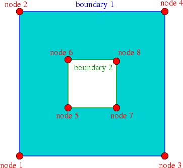
The input file, box_hole.poly, for this domain is:
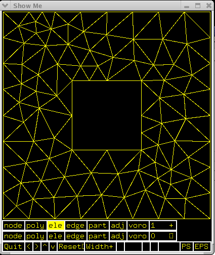
When run as ./triangle -pc -a0.1 -q35 box_hole.poly Triangle creates the output files
box_hole.1.node and
box_hole.1.ele and box_hole.1.poly. Here is a sketch of the resulting triangulation, as displayed by showme :
Creating an oomph-lib mesh based on output files generated by Triangle
oomph-lib provides a mesh, TriangleMesh, that uses the output from Triangle to generate an oomph-lib Mesh containing elements from the TElement<2,NNODE_1D> family of the triangular elements. The relevant interface is:
Example 1: A Poisson problem
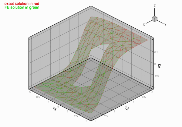
The driver code mesh_from_triangle_poisson.cc demonstrates the use of this mesh for the solution of a 2D Poisson problem in the "rectangular domain with a hole", described in the previous section.
The code expects the names of *.node, *.ele and *.poly files generated by Triangle as command line arguments and stores them in the namespace CommandLineArgs
The names of these files are then passed to the mesh constructor. Since the rest of the driver code is identical to that in the corresponding example with a structured mesh, we do not provide a detailed listing but simply show the plot of the computed results, together with the tanh-shaped exact solution of the problem:
Example 2: A Navier-Stokes problem
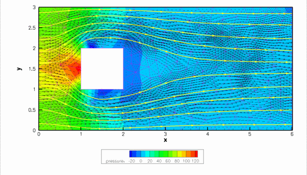
The driver code mesh_from_triangle_navier_stokes.cc demonstrates the use of a TriangleMesh for the solution of a 2D Navier-Stokes problem. The file
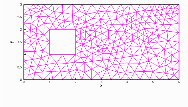
flow_past_box.poly describes a slightly longer box-shaped domain with a hole – representing a 2D channel with an obstruction. In this example the four straight line segments that bound the outer box are given distinct boundary numbers to allow the application of different boundary conditions at the inflow, the outflow, and on the upper and lower no-slip walls.
Here is the mesh, generated by Triangle
...and here is a plot of the flow field (velocity vectors, streamlines and pressure contours) computed with 2D triangular Taylor-Hood elements:
Comments and Exercises
Checking the boundary numbers
We re-iterate that Triangle does not allow nodes to be located on multiple boundaries. It is therefore important to check the boundary numbers allocated by Triangle , e.g. by using the function Mesh::output_boundaries(...). Boundary nodes should always be placed on the boundary with the most restrictive boundary conditions. If this is not possible, some post-processing of the mesh may be required.
Higher-order triangles
Currently, TriangleMesh can be used to generate three, six and ten-node triangles (i.e. triangles with bi-linear, bi-quadratic and bi-cubic shape functions). The generation of ten-node triangles is currently performed somewhat inefficiently and a warning is issued. Developing a more efficient implementation should be straightforward and you are invited to perform this as an exercise.
Exercises
- Download and install
Triangle, and create your own meshes. - Experiment with the options that allow the specification of maximum areas and minimum angles.
Source files for this tutorial
- The source files for this tutorial are located in the directory:
demo_drivers/meshing/mesh_from_triangle/
- The driver code is:
demo_drivers/meshing/mesh_from_triangle/mesh_from_triangle_poisson.cc
PDF file
A pdf version of this document is available. \