In this document we demonstrate how to generate quadrilateral oomph-lib meshes, based on the output from Barry Joe's mesh generator Geompack++, available as freeware at http://members.shaw.ca/bjoe/. The mesh generation is performed in a two-stage process. First we use Geompack++ to generate the mesh "offline". Then we process the output files generated by
Geompack++ to generate an oomph-lib mesh.
Example of the use of Geompack++
The documents meshoper.pdf and regmesh.pdf distributed with Geompack++ contain a comprehensive User's Guide for the code and its many options. Geompack++ is a very sophisticated mesh generator and can be used to create 2D and 3D meshes with a wide variety of element types. Here we only discuss how to use Geompack++ to generate 2D quadrilateral meshes. [The development of of oomph-lib meshes that process Geompack++'s output for other element types should be straightforward but is still on our "To Do" list – any volunteers?]
Geompack++ creates quadrilateral meshes, based on the information about the mesh boundaries (nodes and curves) provided in two input files, filename.rg2 and filename.cs2, say. An output file, filename.1.mh2 is created. It contains the information about the mesh boundaries, the nodal positions and the element connectivity lists.
How to visualise a mesh generated by Geompack++
To visualise the mesh, the program Geomview is available. (Geomview can be downloaded from the Geomview home page .) The Geompack++ output file cannot be processed directly by Geomview but a simple program that converts the file filename.mh2 to a format that is readable by Geomview is available.
The example: A rectangle with a hole
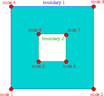
As an example we demonstrate how to use Geompack++ to generate a mesh for the rectangular domain with a hole shown in the figure below. The domain is defined by eight nodes and eight curves (straight lines) which connect the nodes and define two boundaries.
The boundary numbers shown in the sketch correspond to those in the Geompack++ input region file box_hole.rg2 and in the curve input file box_hole.cs2. In the corresponding oomph-lib mesh, the boundaries are numbered from zero.

The desired mesh characteristics are defined in the file box_hole.m2 which specifies that the final mesh should contain approximately 200 elements. When processed with the command
Geompack++ creates the output file box_hole.mh2.
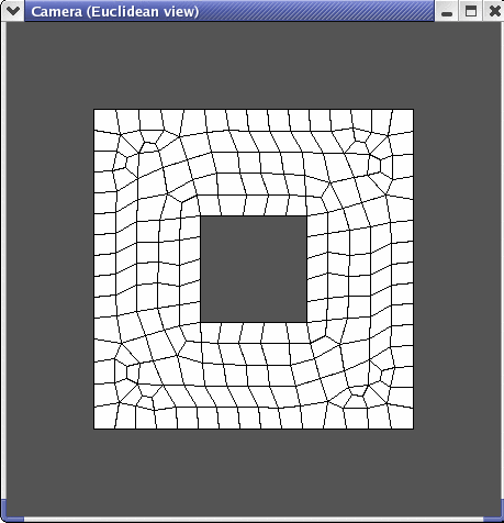
Here is a sketch of the resulting discretisation, as displayed by geomview :

Creating an oomph-lib mesh based on output files generated by Geompack++
oomph-lib provides a mesh, GeompackQuadMesh, that uses the output from Geompack++ to generate an oomph-lib Mesh containing QElement<2,2> four-node quadrilateral elements. The relevant interface is:
The driver code mesh_from_geompack_poisson.cc demonstrates the use of this mesh for the solution of a 2D Poisson problem in the "rectangular domain with a hole", described in the previous section.
The code expects the names of *.mh2 and *.cs2 files generated by Geompack++ as command line arguments and stores them in the namespace CommandLineArgs
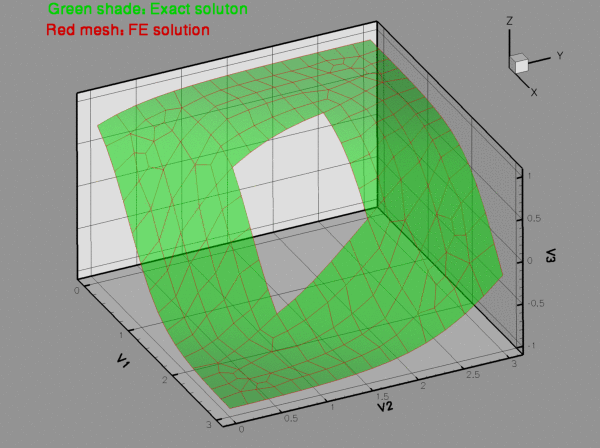
The names of these files are then passed to the mesh constructor. Since the rest of the driver code is identical to that in the corresponding example with a structured mesh, we do not provide a detailed code listing but simply show the plot of the computed results, together with the tanh-shaped exact solution of the problem:

Source files for this tutorial
- The source files for this tutorial are located in the directory:
demo_drivers/meshing/mesh_from_geompack/
- The driver code is:
demo_drivers/meshing/mesh_from_geompack/mesh_from_geompack_poisson.cc
PDF file
A pdf version of this document is available. \